Method for laminating pole core of generator rotor of hydroelectric generating set before pre-pressing

A technology of generator rotor and magnetic pole iron core, applied in the direction of manufacturing stator/rotor body, etc., can solve the problems of unsafe, inconvenient operation of vertical laminations, and the position and quantity cannot meet the size requirements, so as to improve the quality and The effect of production efficiency

Inactive Publication Date: 2010-06-30
TIANJIN TIRNFR HEAVY HYDROELECTRIC FRCILITY CO LTD
View PDF0 Cites 5 Cited by
  • Summary
  • Abstract
  • Description
  • Claims
  • Application Information

AI Technical Summary

Problems solved by technology

The characteristic of this process method is that the magnetic pole punching piece is directly penetrated into the tightening screw for loading and pressing. The method has the following disadvantages: (1) For the rotor magnetic pole core of large and medium-sized hydroelectric units, the length of the magnetic pole core will increase with the increase of the capacity of the unit. It has even increased to more than 2 meters, and the vertical lamination operation is very inconvenient and unsafe.
(2) Due to the design strength requirements of the rotor pole core of large and medium-sized hydropower units, various pole punches of different shapes are added, and different surface shapes are formed on the surface of the pole core according to the design requirements and sizes. There is a fixed position in the middle. The position and quantity of the various pieces placed on the vertical lamination before pre-pressing often cannot meet the size requirements of each part after pressing, and changing the number of these punching pieces is due to the penetration of the tensioning screw. quite time-consuming

Method used


Image

  • Method for laminating pole core of generator rotor of hydroelectric generating set before pre-pressing
  • Method for laminating pole core of generator rotor of hydroelectric generating set before pre-pressing
  • Method for laminating pole core of generator rotor of hydroelectric generating set before pre-pressing

Examples


Embodiment 1

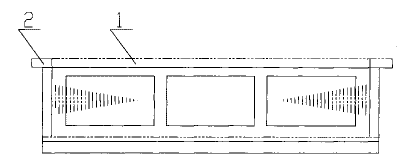
[0025] A hydroelectric generator rotor magnetic pole core lamination method before preloading, the adjustment piece is filled into the magnetic pole core, and the process is as follows:

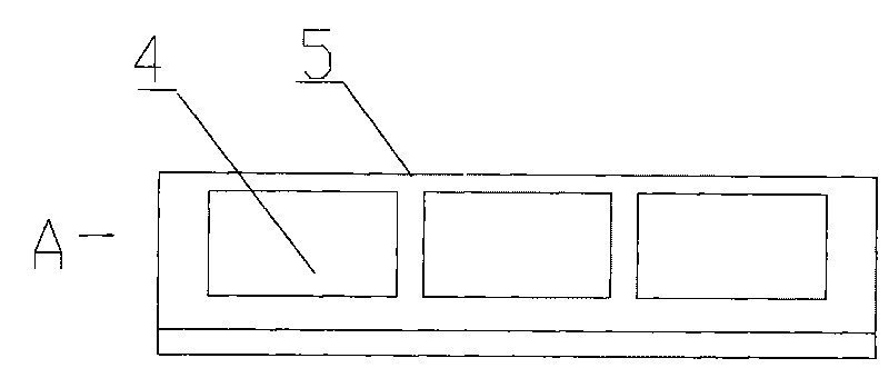
[0026] 1) Place the frame 5 in a horizontal direction, with a detection hole 4 in the middle of the frame 5, and two parallel ribs on the upper part, which are used to support the lower end surface of the magnetic pole punching piece pole shoe, so that the magnetic pole punching pieces are neat and consistent;

[0027] 2) The magnetic pole pressing plate 2 compresses the pre-stacked magnetic pole punching piece 1, and the size error and shape error of each part are measured by the feeler gauge 3;

[0028] 3) Add an adjustment sheet in the middle of the pre-stacked magnetic pole punching sheet on the shelf (the adjustment sheet is spot-welded with the adjacent sheet);

[0029] 4) After penetrating the magnetic pole tensioning screw and damping strip, pressurization is completed.

[0030] The ...


PUM


Abstract

The invention relates to a method for laminating the pole core of the generator rotor of a hydroelectric generating set before pre-pressing, belonging to the technical field of generators. The method for laminating the pole core of the generator rotor of the hydroelectric generating set before pre-pressing is that adjustment sheets are filled in the pole core, and is characterized in that: 1) a horizontal placing rack is adopted, and two parallel ribs are arranged at the upper part of the placing rack and are used to support the lower end surfaces of the pole shoes of pole laminations to enable the pole laminations to be tidy and uniform; 2) the pre-laminated pole laminations are tightly pressed, and the deviations of the dimension and the form of all parts from the required dimension and the required form are measured; 3) the adjustment sheets are added among the pole laminations pre-laminated on the placing rack; and 4) the pole core is assembled and pressed after the pole core is penetrated through a pole tie bolt and damper bars. The invention has the advantages that the method is simple, the requirements on the lamination of different types of pole laminations are satisfied, the assembling quality of the pole core is good, the production efficiency is high and the like.

Description

technical field [0001] The invention belongs to the technical field of generators, and in particular relates to a lamination method before preloading of a magnetic pole iron core of a generator rotor of a hydroelectric unit. Background technique [0002] At present, before preloading the rotor magnetic pole core of the generator set, one end of the magnetic pole tightening screw is used to screw the nut into the nut, and after penetrating the magnetic pole pressing plate at one end, the tensioning screw is erected, and then the rotor magnetic pole core punching piece is inserted from top to bottom and pulled. Tighten the screw, put it into the other end of the magnetic pole pressure plate, tighten the tension nut, and send it to the next sequence for loading. The characteristic of this process method is that the magnetic pole punching piece is directly penetrated into the tightening screw for loading and pressing. The method has the following disadvantages: (1) For the rotor...

Claims


Application Information

Patent Timeline
Patent Type & Authority Applications(China)
IPC IPC(8): H02K15/02
Inventor 赵作勤
Owner TIANJIN TIRNFR HEAVY HYDROELECTRIC FRCILITY CO LTD
Why Eureka
Try Eureka