Automatic strapping packing machine and automatic strapping packing system

A packaging system and packaging machine technology, applied in the direction of packaging machines, packaging, transportation and packaging, etc., can solve the problems of complex structure, poor supply, cost, etc., and achieve simplification of device structure, reduction of installation space, and simple structure the effect of

Active Publication Date: 2010-06-30
STRAPACK SHIMOJIMA CO LTD
View PDF4 Cites 5 Cited by
  • Summary
  • Abstract
  • Description
  • Claims
  • Application Information

AI Technical Summary

Problems solved by technology

[0047] However, in the automatic banding packaging machine 300 of Patent Document 2, there is such a problem that the structure of the tilting movement mechanism for tilting the band guiding arch 302 is complicated, and due to considerations of durability and safety, However, the size of the device is increased, and the cost
[0048] In addition, in the automatic banding packaging machine 400 of Patent Document 3, there is such a problem that the band guide arch 402 is set upright behind the upper table 404, so that the corners are increased, and the band is supplied into the band guide arch. poor supply
[0049] In addition, in the automatic banding packaging machine 500 of Patent Document 4, the inner arch body 504 and the other outer arch body 506 are in a cross vertically intersecting structure, so as Figure 18 As shown, the protruding mechanism 508 of the inner arch body 504 and the gap portion 510 of the outer arch body 506 need to be fitted, and the protrusion mechanism of the inner arch body 504 needs to be inserted in the middle of the band guide part 512 of the outer arch body 506 The short strap guide part 514 in 508, the strap guide part 512 communicates with the short strap guide part 514, and the complex structure that the strap can wrap around in the outer arch body 506 also increases the cost

Method used


Image

  • Automatic strapping packing machine and automatic strapping packing system
  • Automatic strapping packing machine and automatic strapping packing system
  • Automatic strapping packing machine and automatic strapping packing system

Examples


Embodiment Construction

[0205] Hereinafter, embodiments (examples) of the present invention will be described in detail with reference to the drawings.

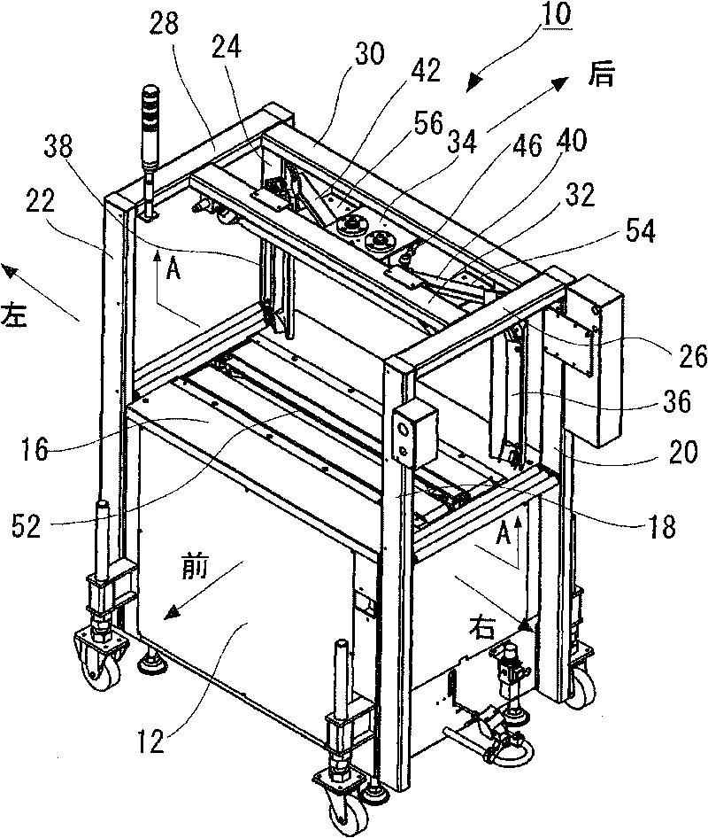
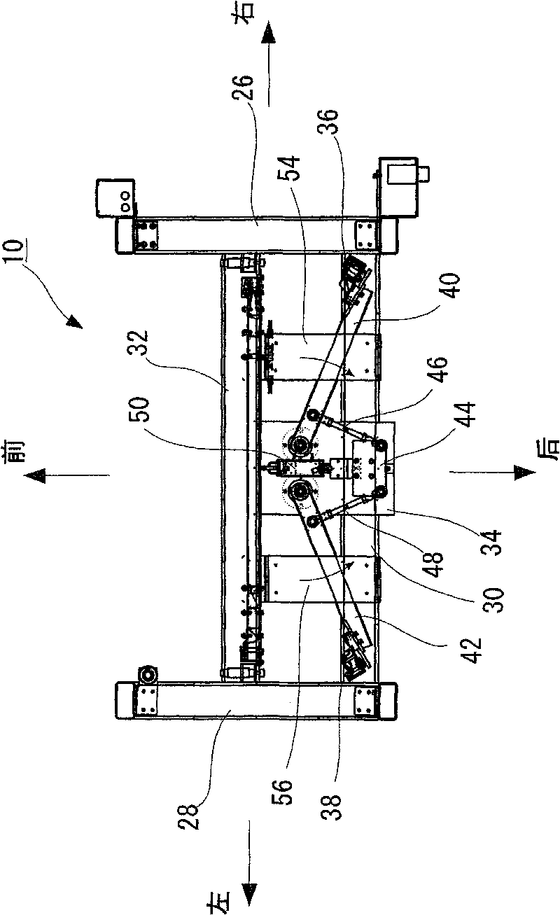
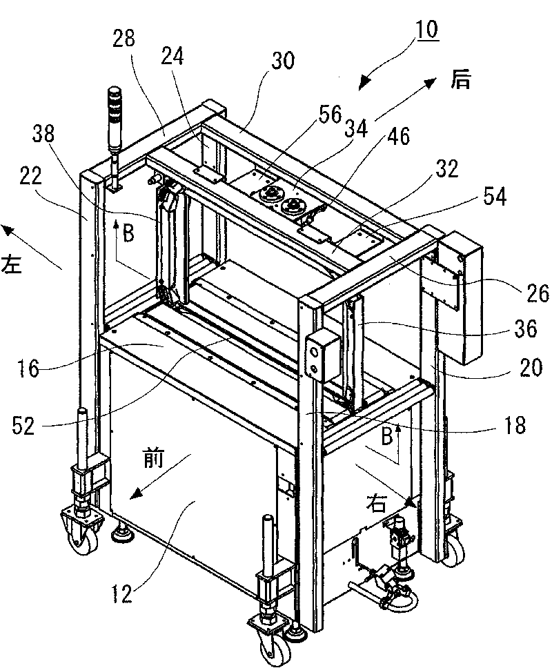
[0206] figure 1 It is a perspective view showing the state in which the vertical strap guiding arch of the automatic strapping packaging machine of the present invention is located at the standby position, figure 2 From figure 1 The rear view viewed from the A-A direction, image 3 It is a perspective view showing the state of the automatic banding packaging machine of the present invention in a communication position, Figure 4 From image 3 The rear view of the B-B direction.

[0207] exist figure 1 In , reference numeral 10 generally denotes the automatic banding packaging machine of the present invention.

[0208] Such as figure 1 As shown, the automatic banding packaging machine 10 includes, for example, a packaging machine main body 12 installed on the ground of a factory or the like. On the upper surface of the packaging machine m...


PUM


Abstract

The invention provides an automatic strapping packing machine in which the carrying line of packed articles can be arranged in the straight line direction while reducing the installation space and simplifying the total structure, a band can be fed surely into a band guide arch, and packing work can be performed continuously, and to provide its automatic strapping packing system. The automatic strapping packing machine includes a packing machine body having an upper surface table on which packed articles pass, a pair of vertical band guide arches arranged above the upper surface table in the direction parallel with the passing direction of the packed articles while spaced apart from each other, and a horizontal band guide arch arranged above the upper surface table in the direction parallel with the passing direction of the packed articles wherein the pair of vertical band guide arches are arranged freely to move between a waiting position separated from the horizontal band guide arch and a communicating position communicating with the horizontal band guide arch in the direction intersecting the passing direction of the packed articles perpendicularly.

Description

technical field [0001] The invention relates to an automatic banding packaging machine and an automatic banding packaging system. Background technique [0002] In the past, along with the labor-saving of packing operation, for example patent document 1 (Japanese Patent Laying-Open No. Hei 5-112315) discloses, generally widely used such as Figure 12 An automatic strapping packaging machine 100 is shown. [0003] That is, the automatic strapping packaging machine 100 is as Figure 12 As shown, there is a packaging machine main body 101 installed on the ground of a factory, for example, and an upper table 114 constituting a workbench for placing and packaging objects to be packaged is formed on the upper surface of the packaging machine main body 101 . [0004] In addition, a substantially U-shaped band guide arch 102 is erected on the top table 114, and although not shown, a continuous band passage is formed therein. [0005] That is, the strap guide arch 102 is composed of ...

Claims


Application Information

Patent Timeline
Patent Type & Authority Applications(China)
IPC IPC(8): B65B13/14B65B13/18
CPCB65B65/003B65B13/06B65B13/18B65B13/14
Inventor 山本京钟相泽义胜佐藤充飞田英二
Owner STRAPACK SHIMOJIMA CO LTD
Why Eureka
Try Eureka