Refrigeration cycle device

A refrigeration cycle and refrigerant technology, used in refrigerators, refrigeration components, refrigeration and liquefaction, etc., can solve the problems of less refrigerant and poor power recovery efficiency, and achieve the effect of improving the degree of freedom of design

Inactive Publication Date: 2010-06-30
PANASONIC CORP
View PDF10 Cites 7 Cited by
  • Summary
  • Abstract
  • Description
  • Claims
  • Application Information

AI Technical Summary

Problems solved by technology

[0008] However, if part of the refrigerant flows into the bypass circuit 911, the amount of refrigerant that contributes to power recovery in the expander 905 decreases, and there is a problem that power recovery efficiency deteriorates.
This problem is noticeable, for example, in the case where refrigeration cycle devices of the same design are applied to heat pump warm water floor heaters and air conditioners, respectively.

Method used


Image

  • Refrigeration cycle device
  • Refrigeration cycle device
  • Refrigeration cycle device

Examples


no. 1 approach

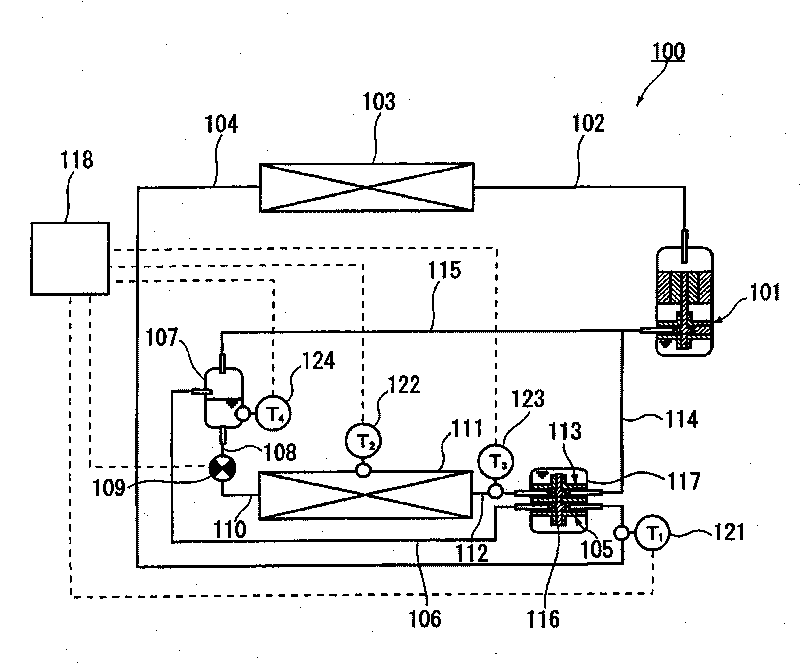
[0048] Such as figure 1 As shown, the refrigeration cycle device 100 includes: a high-pressure stage compressor 101 , a radiator 103 , an expander 105 , a gas-liquid separator 107 , an expansion valve 109 , an evaporator 111 , and a low-pressure stage compressor 113 .

[0049] The low-pressure stage compressor 113 pre-compresses the gas refrigerant evaporated in the evaporator 111 . The high-pressure stage compressor 101 further compresses the refrigerant (working fluid) precompressed by the low-pressure stage compressor 113 . The expander 105 recovers power by expanding the refrigerant cooled by the radiator 103 . In addition, the expander 105 is configured to pass the entire amount of the refrigerant cooled by the radiator 103 . That is, a bypass circuit for flowing the refrigerant bypassing the expander 105 is not provided. Since the entire amount of the refrigerant contributes to the power recovery, the improvement effect of the COP (coefficient of performance) by the ...

no. 2 approach

[0109] Figure 9 It is a block diagram of the refrigeration cycle apparatus of 2nd Embodiment of this invention. The refrigeration cycle device 500 of the present embodiment has the same structure as the refrigeration cycle device 100 of the first embodiment (refer to figure 1 ) roughly the same structure. This embodiment differs from the first embodiment in that the temperature sensor 520 and the control by the controller 118 are provided. Hereinafter, the same reference numerals are assigned to the same functional components, and description thereof will be omitted.

[0110] like Figure 9 As shown, the refrigeration cycle apparatus 500 includes a temperature sensor 520 for detecting the temperature of the refrigerant discharged from the high-pressure stage compressor 101 . Similar to the first embodiment, a temperature sensor 122 for detecting the evaporation temperature of the refrigerant in the evaporator 111 is also provided. The controller 118 controls the opening...

no. 3 approach

[0116] Figure 11 It is a configuration diagram of a refrigeration cycle apparatus according to a third embodiment of the present invention. The refrigeration cycle device 700 has substantially the same configuration as the refrigeration cycle devices described in the first and second embodiments. This embodiment differs from the first embodiment in that the high-pressure stage compressor 701 , the low-pressure stage compressor 713 , and the expander 705 are housed in a common airtight container 717 .

[0117] like Figure 11 As shown, in the refrigeration cycle apparatus 700, the high-pressure stage compressor 701, the low-pressure stage compressor 713, and the expander 705 are arranged in a single airtight container 717 in this order from the top. The low pressure stage compressor 713 and the expander 705 are connected by a shaft 716 and can transmit power through the shaft 716 . Oil is accumulated at the bottom of the airtight container 717 . The space above the oil sur...


PUM


Abstract

Disclosed is a refrigeration cycle device (100) comprising a low-pressure stage compressor (113), a high-pressure stage compressor (101), a radiator (103), a gas-liquid separator (107), an expansion valve (109), an expander (105), and an evaporator (111). The low-pressure stage compressor (113) and the expander (105) are coupled by a shaft (116), and the low-pressure stage compressor (113) is driven by power recovered from the refrigerant by the expander (105). The low-pressure stage compressor (113) and the high-pressure stage compressor (101) are connected in series by an intermediate-pressure flow channel (114). The gas-liquid separator (107) and the intermediate-pressure flow channel (114) are connected by a reciprocating flow channel (115). The reciprocating flow channel (115) is configured to allow the bidirectional flow of refrigerant therethrough. The refrigerant flow rate through the reciprocating flow channel (115) is regulated by controlling the degree of opening of the expansion valve (109).

Description

technical field [0001] The invention relates to a refrigeration cycle device. Background technique [0002] As a refrigeration cycle device for air conditioners and water heaters, such as Figure 13 As shown, a device having a first compressor 801a, a radiator 802, an expander 803, a heat absorber 804, and a second compressor 801b is known (Patent Document 1). The second compressor 801b is connected to the expander 803 via a rotary shaft 806, and the driving force of the second compressor 801b is provided by the power of the expander 803 accompanying the expansion of the refrigerant. Therefore, it is possible to reduce the power consumption of the first compressor 801a for raising the pressure of the refrigerant to a predetermined pressure. [0003] according to Figure 13 In the refrigeration cycle device shown, the rotation speed of the expander 803 is consistent with the rotation speed of the second compressor 801b. In addition, since the refrigerant expanded in the exp...

Claims


Application Information

Patent Timeline
Patent Type & Authority Applications(China)
IPC IPC(8): F25B1/10F25B11/02
CPCF25B2400/23F25B9/06F25B2700/2117F25B2600/2513F25B2700/2109F25B2700/21151F25B2700/21152F25B1/10F25B2400/14F25B2309/061
Inventor 冈市敦雄高桥康文尾形雄司和田贤宣引地巧
Owner PANASONIC CORP
Why Eureka
Try Eureka