
Independent power supply system

An independent power supply and power control technology, applied in the direction of circuits, collectors, photovoltaic power generation, etc., can solve the problems that the control circuit cannot detect the increase of power generation, cannot monitor the battery voltage or power generation, and cannot supply power to the load.

Inactive Publication Date: 2010-06-30
PANASONIC CORP
View PDF1 Cites 14 Cited by
  • Summary
  • Abstract
  • Description
  • Claims
  • Application Information

AI Technical Summary

Problems solved by technology

Also, if the control circuit stops working, it is impossible to monitor the battery voltage or power generation
In this way, even if the amount of power generation increases again due to changes in the natural environment, the control circuit cannot detect the increase in power generation, and as a result, the discharge of the battery remains prohibited, and there is a problem that power cannot be supplied to the load.

Method used

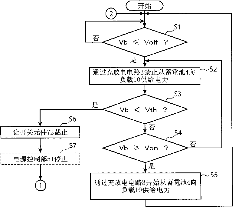

Image

  • Independent power supply system
  • Independent power supply system
  • Independent power supply system

Examples


no. 1 example

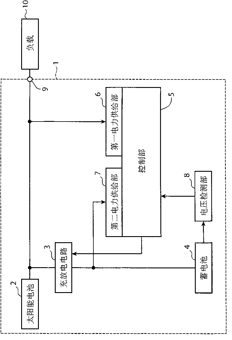
[0016] figure 1 It is a block diagram showing an example of the configuration of the independent power supply system according to the first embodiment of the present invention. figure 1 The shown independent power supply system 1 includes a solar cell 2 (power generation unit), a charging and discharging circuit 3, a storage battery 4, a control unit 5, a first power supply unit 6 (a first operating power supply unit), and a second power supply unit 7. (second operating power supply unit), voltage detection unit 8 and connection terminal 9 . Furthermore, a load 10 is connected to the connection terminal 9 . The independent power supply system 1 may also include the load 10 , or may be an independent device including the load 10 .

[0017] The solar cell 2 is a power generation unit that generates power based on sunlight as an example of natural energy. The solar battery 2 supplies the generated power to the charge and discharge circuit 3 , the first power supply unit 6 , an...

no. 2 example

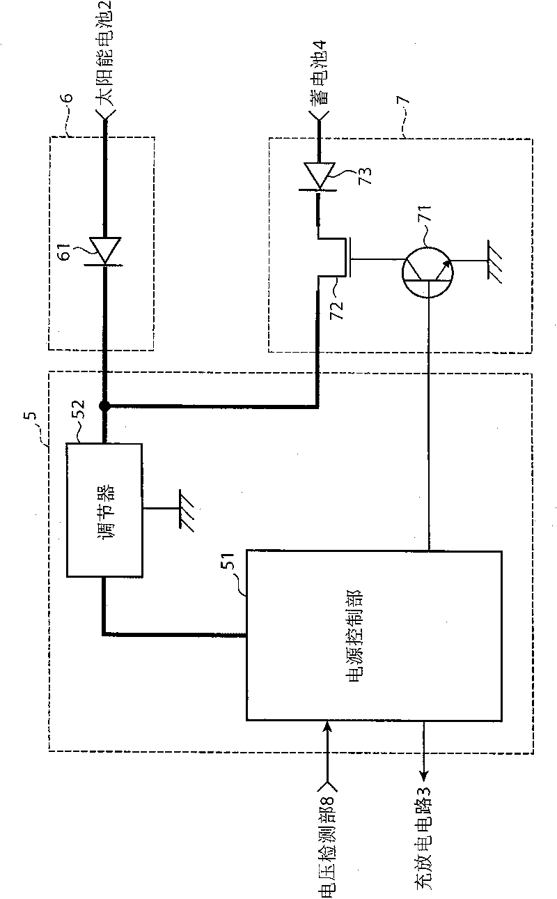
[0047] Next, an independent power supply system according to a second embodiment of the present invention will be described. Figure 5 It is a block diagram illustrating an example of the configuration of the control unit 5, the first power supply unit 6, the second power supply unit 7, and the natural power supply inhibiting unit 11 of the independent power supply system 1a according to the second embodiment of the present invention. The stand-alone power supply system 1 a according to the second embodiment of the present invention differs from the stand-alone power supply system 1 in that it further includes a natural power supply inhibiting unit 11 .

[0048] Such as Figure 5 As shown, the natural power supply prohibition section 11 in the independent power supply system 1 a is provided between the solar battery 2 and the first power supply section 6 . Figure 5 The shown natural power supply inhibiting unit 11 includes a Zener diode 12 and a capacitor 13 (electric storag...


PUM


Abstract

An independent power supply system comprises a power source control unit (51) for controlling discharge to a connection terminal (9) of a battery (4), a first power supply unit (6) for supplying an electric power generated by a solar battery (2) to the power source control unit (51) as an operation power, a second power supply unit (7) for supplying an electric power stored in the battery (4) to the power source control unit (51) as the operation power, and a switching element (72) for inhibiting the second power supply unit (7) from supplying the operation power to the power source control unit (51) when the terminal voltage of the battery (4) does not meet an operational voltage threshold. During a period in which the switching element (72) turns off and stops operating, when the electric power generated by the solar battery (2) is supplied by the first power supply unit (6), the power source control unit (51) is activated to turn on the switching element (72).

Description

technical field [0001] The present invention relates to an independent power supply system that charges a storage battery with electric power generated by natural energy such as sunlight or wind power, and supplies electric power to various external loads such as cameras and sensors. Background technique [0002] Conventionally, an independent power supply system that uses natural energy such as sunlight or wind power to store electricity can independently supply electricity without receiving electricity from a power company. Therefore, such an independent power supply system is used as a power supply device that can be easily installed outdoors without the need for electric wire laying works managed by the electric power company. Such an independent power supply system uses natural energy such as solar cells or windmills to generate electricity, so the amount of power generated varies due to changes in various natural environments such as weather, seasons, and climates in t...

Claims


Application Information

Patent Timeline
Patent Type & Authority Applications(China)
IPC IPC(8): H02J7/00H01M10/44H02H7/18H02J7/35
CPCY02E60/12H01M10/465H02J7/35H01M10/425Y02E10/566H01M10/44Y02E10/56Y02E60/10
Inventor 前川和也
Owner PANASONIC CORP
Learn More