Method for simulating solid phase movement in steel ingot

A simulation method and technology for steel ingots, which are applied in special data processing applications, instruments, electrical digital data processing, etc., and can solve problems such as large cutting tail rate of large steel ingots

Active Publication Date: 2010-07-07
INST OF METAL RESEARCH - CHINESE ACAD OF SCI
View PDF0 Cites 15 Cited by
  • Summary
  • Abstract
  • Description
  • Claims
  • Application Information

AI Technical Summary

Problems solved by technology

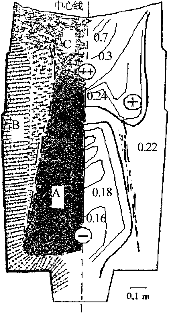
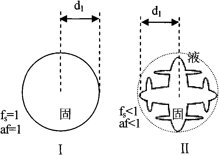
[0004] The purpose of the present invention is to provide a simulation method for solid phase movement in steel ingots, quickly and effectively predict the deposition pile of steel ingots, and solve the problem of large tail cutting rate of large steel ingots in factories

Method used


Image

  • Method for simulating solid phase movement in steel ingot
  • Method for simulating solid phase movement in steel ingot
  • Method for simulating solid phase movement in steel ingot

Examples


Embodiment 1

[0126] Such as Figure 8 As shown, the inner side of the clay sand mold 6 is used for pouring molten metal to form a steel ingot 2 , the top of the steel ingot 2 is covered with a thermal insulation covering agent 7 , and the side of the top of the steel ingot 2 is provided with thermal insulation bricks 8 .

[0127]The material of the steel ingot mold is clay sand, the preheating temperature of the steel ingot mold is 50°C, the riser adopts thermal insulation riser, the taper of the steel ingot is 1.5%, the ratio of height to diameter of the steel ingot is 2.2:1, the height of the bottom cone of the steel ingot is 22cm; the weight of pouring molten metal is 13 tons , superheating temperature is 30℃, by weight percentage, alloy steel chemical composition: C: 0.22%, Si: 0.20%, Mn: 1.45%, Mo: 0.5%, Ni: 0.75%, Cr: 0.15, P≤0.005% , S≤0.002%, Fe balance. The top of the riser is filled with insulation covering agent, and the sides of the riser are insulation bricks.

[0128] by ...

Embodiment 2

[0135] Such as Figure 11 As shown, the inner side of the water glass sand mold 9 is used for pouring molten metal to form a steel ingot 2, and the top of the steel ingot 2 is covered with a thermal insulation riser 10 (including a thermal insulation covering agent).

[0136] The material of the steel ingot mold is sodium silicate sand, the preheating temperature of the steel ingot mold is 100°C, the riser adopts thermal insulation riser, the material is high alumina brick, corundum and mullite, the taper of the steel ingot is 1.5%, and the height-to-diameter ratio of the steel ingot is 2.0:1 ; The weight of pouring molten metal is 500kg, the superheating temperature is 50°C, and the chemical composition of alloy steel is calculated by weight percentage: C: 0.45%, Si: 0.20%, Mn: 0.51%, P≤0.02%, S≤0.02%, Fe quantity. The filling material above the riser is thermal insulation covering agent of high alumina brick, corundum or mullite.

[0137] by Figure 11 The steel ingot sho...


PUM


Abstract

The invention relates to a steel ingot solid phase movement simulation technology, in particular to a method for simulating solid phase movement in a steel ingot, which is used in the casting process of carbon steel and alloy steel ingot under vacuum and non-vacuum conditions. The method comprises the following steps: determining the solid phase movement critical speed and movement termination critical solid phase fraction of alloy; calculating mass, momentum, energy and component conservation equations and calculating a solid phase fraction field; determining an initiating position for forming a sedimentarypile on the gravity direction; taking the initiating position as a boundary to divide the steel ingot into an upper part and a lower part; reducing solid phase fraction and solid phase components, increasing liquid phase components for a grid cell in which the liquid flow rate is less than the solid phase movement critical speed and the solid phase fraction is larger than zero but smaller than the movement termination critical solid phase fraction along the gravity direction at the upper part of the steel ingot, and performing temperature transfer with a bottom cell; and increasing solid phase fraction and solid phase components, reducing liquid phase components for a grid cell in which the solid phase fraction is smaller than the movement termination critical solid phase fraction at the lower part of the steel ingot, and performing temperature transfer with a top cell.

Description

technical field [0001] The invention relates to a simulation technology for solid phase movement in steel ingots, specifically a method for simulating solid phase movement in steel ingots, which can simulate solid phase movement in steel ingots without solving a two-phase flow model, thereby predicting the bottom sedimentation pile , involving casting processes of metal and non-metal molds of all levels below 360 tons, applied to the casting process of carbon steel and alloy steel ingots under vacuum and non-vacuum conditions, and can quickly and accurately predict the bottom deposition pile of steel ingots of various metal materials. Background technique [0002] During the solidification process of a large steel ingot, due to the movement of the solid phase, when there is a difference in mass density between the crystal grains and the melt, the free crystals with low composition sink continuously and accumulate at the bottom, reducing the solute concentration in this area a...

Claims


Application Information

Patent Timeline
Patent Type & Authority Applications(China)
IPC IPC(8): B22D7/06G06F19/00
Inventor 刘东戎桑宝光康秀红李殿中
Owner INST OF METAL RESEARCH - CHINESE ACAD OF SCI
Why Eureka
Try Eureka