
Water area deoiling unit and its combined oil dam

A water area and oil removal tank technology, which is used in the cleaning of open water surfaces, water conservancy projects, general water supply conservation, etc., to achieve the effects of convenient disassembly and assembly, efficient oil removal operation, and simple structure

Inactive Publication Date: 2011-12-28
TSINGHUA UNIV
View PDF8 Cites 0 Cited by
  • Summary
  • Abstract
  • Description
  • Claims
  • Application Information

AI Technical Summary

Problems solved by technology

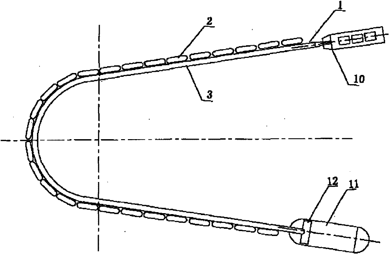
[0007] Aiming at the shortcomings of the above-mentioned general oil containment and oil retention devices in terms of oil retention and oil removal and treatment of polluted water bodies, the present invention designs a water area oil removal unit and its combined oil retention dam, which has the functions of oil retention and oil collection at the same time

Method used


Image

  • Water area deoiling unit and its combined oil dam
  • Water area deoiling unit and its combined oil dam
  • Water area deoiling unit and its combined oil dam

Examples


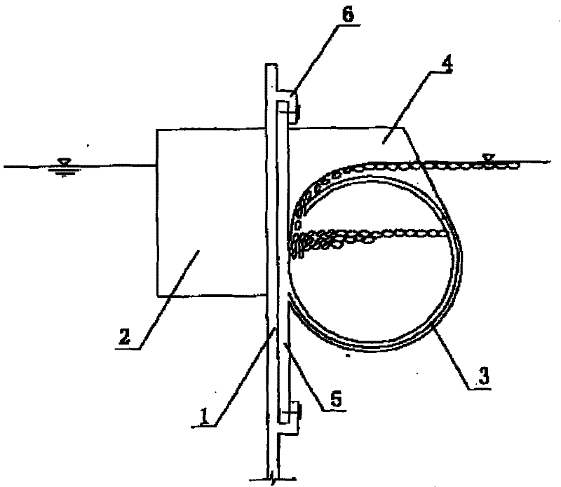
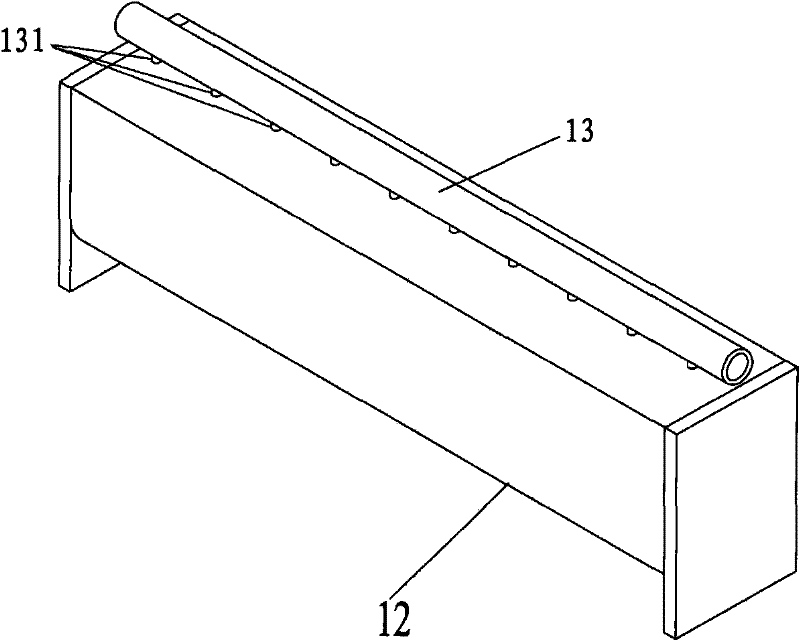
Embodiment Construction

[0027] The present invention will be further described in detail below in conjunction with the accompanying drawings and specific embodiments.

[0028] image 3 and Figure 4 They are respectively a perspective view and a vertical section view of the water area degreasing unit in the present invention. like image 3 and Figure 4 As shown, the water area oil removal unit provided by the present invention includes an oil removal tank 1, an oil suction pipe 13 and an oil suction branch pipe 131; wherein the oil suction pipe 13 is arranged on the top of the oil removal tank 1, and the oil suction branch pipe 131 is for connecting the cavity of the oil removal tank and the oil suction pipe cavity The connection passage, the oil suction pipe 13 is connected with the inner cavity of the oil removal tank 1 through uniformly distributed oil suction branch pipes 131 . The pipe material of oil suction pipe 13 can adopt FRP (or UPVC).

[0029] like Figure 4 As shown, the degreasin...


PUM


Abstract

The invention provides a water area oil removing unit and an oil retention dam which is formed by combining same. The water area oil removing unit comprises an oil removing tank, an oil suction pipe and an oil suction branch pipe; the oil suction pipe is positioned above the oil removing tank; the oil suction branch pipe is a connection passage which connects a cavity of the oil removing tank with a cavity of the oil suction pipe; the oil removing tank comprises a curve baffle and an perforated wall; and the curve baffle is an inward bent part on a tank side of the oil removing tank, and the perforated wall is a baffle part with an opening on the other tank side of the oil removing tank. The solution of the invention has the functions of oil retention and oil removal; the water area oil removing unit and the oil retention dam have the advantages of simple structure and convenient assembly and disassembly; and after adopting the scheme, purification operation of water regions of oil spilling rivers in different areas can be implemented, and the specially designed oil removing tank enables the oil removal operation of the water regions to be more efficient.

Description

technical field [0001] The invention relates to the technical field of oil removal in river waters, in particular to a water area oil removal unit with the functions of oil confinement and oil collection and an oil retaining dam composed of the same. Background technique [0002] When ship oil spill accidents and chemical dangerous goods leakage occur in coastal waters, inland rivers, ports and other waters, a large amount of spilled crude oil and diesel oil will form oil slicks on the water surface, which will pollute and seriously damage the environment, requiring emergency control and oil recovery. [0003] The difference in specific gravity is used to remove the oil slick on the water surface with a vacuum pump. This method can quickly remove a large area of ​​oil slick on the water surface and improve the oil removal effect, but it cannot solve the problem of oil slick diffusion. [0004] Existing emergency control is to deploy oil booms or booms etc. quickly to enclose...

Claims


Application Information

Patent Timeline
Patent Type & Authority Patents(China)
IPC IPC(8): E02B15/04
CPCY02A20/204
Inventor 刘文君刘书明吴雪
Owner TSINGHUA UNIV
Learn More