Electric valve

An electric valve, valve body technology, applied in the direction of lift valve, valve details, valve device, etc., can solve the problems of inability to realize the miniaturization of electric valve, increase the height of electric valve, etc., and achieve easy welding and release the shortage of compressive strength. , to ensure the effect of bonding strength

An electric valve, valve body technology, applied in the direction of lift valve, valve details, valve device, etc., can solve the problems of inability to realize the miniaturization of electric valve, increase the height of electric valve, etc., and achieve easy welding and release the shortage of compressive strength. , to ensure the effect of bonding strength

CN101769388AInactive Publication Date: 2010-07-07ZHEJIANG SANHUA INTELLIGENT CONTROLS CO LTD

Image

  • Electric valve
  • Electric valve
  • Electric valve

Examples


Embodiment Construction

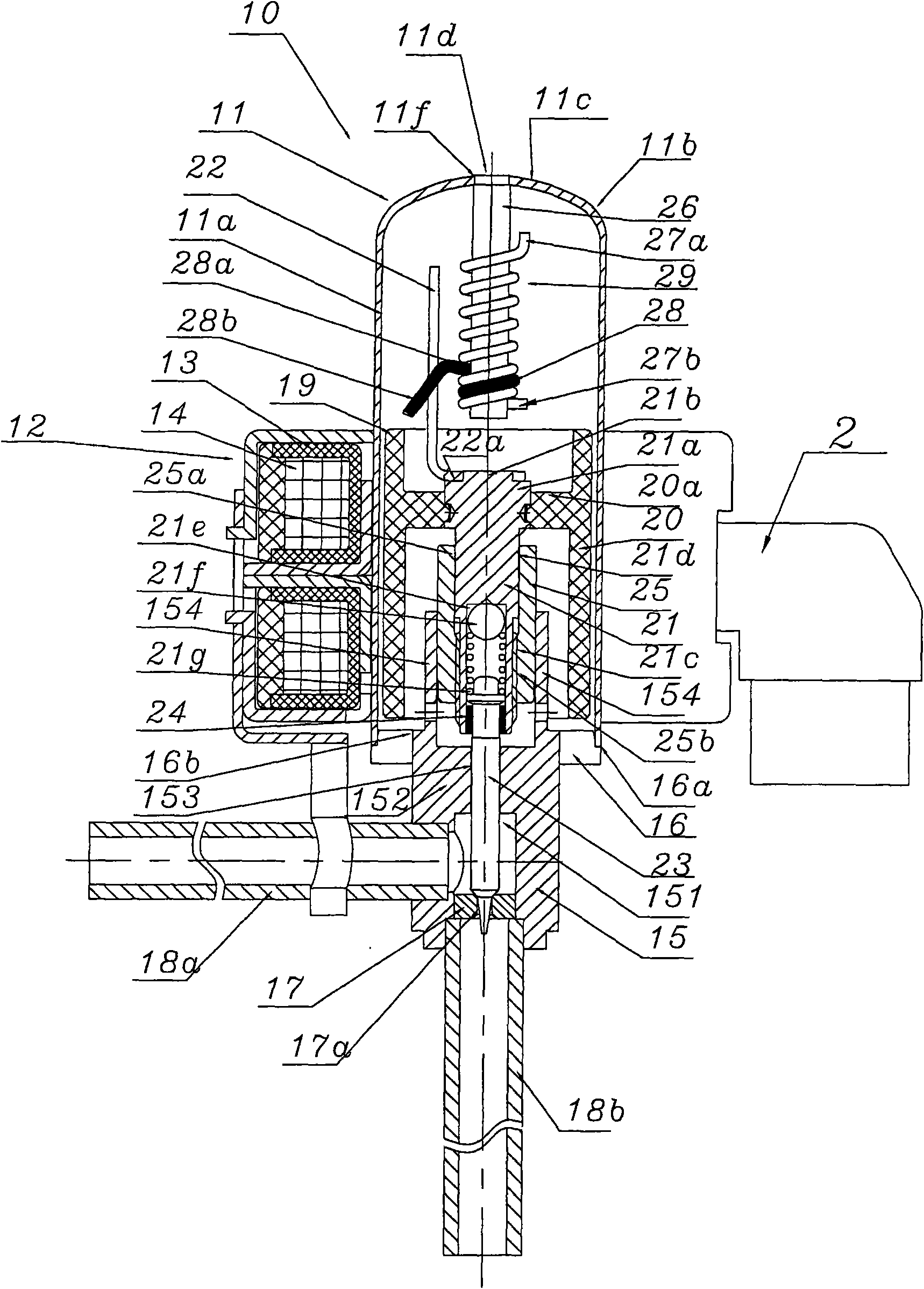
[0052] Below, refer to Figure 1a , Figure 1b , Figure 1c as well as Figure 1d , specifically explain the specific implementation of the electric valve of the present invention.

[0053] Such as Figure 1a As shown, the electric valve represented by the symbol 10 as a whole includes a cylindrical airtight cover 11 formed by stamping metal such as stainless steel, a stator part 12 installed on the outer periphery of the cover 11; a stator yoke 13 of the stator part 12 There is a stator coil 4 inside, and the electric valve is basically the same as the said existing electric valve, so the detailed description is omitted.

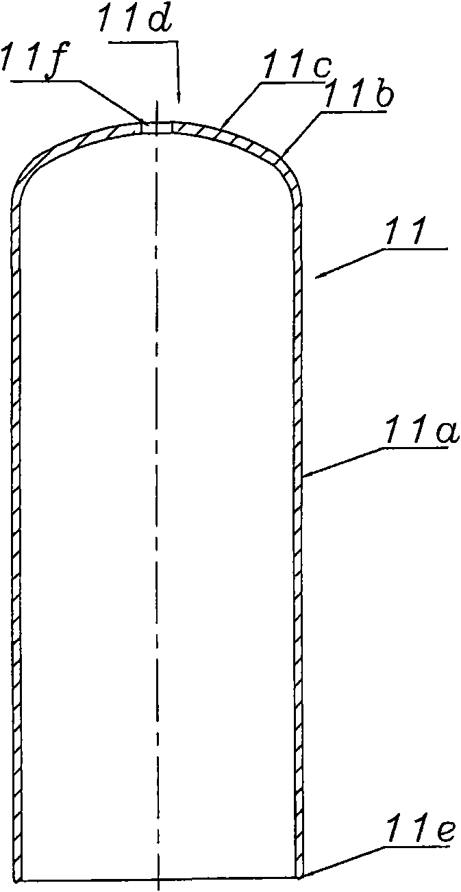
[0054] Such as Figure 1b As shown, the outer cover 11 forming the airtight space is generally composed of a cylindrical wall portion 11a of stainless steel material with a wall thickness of 1 mm, a curved portion 11b integrally connected with the cylindrical wall portion 11a, and an arc portion 11c. Moreover, the arc portion 11c is the top 11d correspo...


PUM


Abstract

The invention discloses an electric valve. A rotor forming a step motor and a valve needle are arranged in a sealed space formed by an outer shell, the bottom of the outer shell is fixed on a valve body, the valve needle approaches or is apart from a valve seat of the valve body according to the upward and downward axial movement of the rotor, and a shaft member forming a stopping mechanism is taken as a rotation stopping mechanism of the rotor and is fixed at the top of the outer shell in a drooping state in the outer shell; the outer shell forming the seal space consists of a cylinder wall, a bending part and an arc part, and the bending part is formed by connecting the cylinder wall; and the circular edge of the bottom of the cylinder wall is fixed on the valve body, the arc part forms the top of the outer shell, and the fixation of the shaft member is implemented by laser welding.

Description

technical field [0001] The invention relates to an electric valve, in particular to an electric valve suitable for controlling the flow of refrigerant in a refrigeration cycle of natural refrigerant such as carbon dioxide (CO2). Background technique [0002] In the refrigeration cycle, an electric valve used as a flow control valve includes a valve body, a valve core or a valve needle that is close to or away from a valve seat formed on the valve body, and a cylindrical casing (closed) fixed on the valve body. Type outer cover), and the rotor that is arranged in this outer cover, and the stator that is arranged on the outside of described airtight type outer cover and its rotor opposite configuration; Described rotor and stator constitute stepping motor, moreover, the Inside, there is a stop mechanism as a rotation stop mechanism of the rotor, and the stop mechanism limits the rotation range of the rotor and stops the vertical movement of the valve needle. [0003] There ar...

Claims


Application Information

Patent Timeline
07 Jul 2010
Publication
CN101769388A
IPC
F16K1/38; F16K31/04; F16K27/02; F25B41/04
Inventors
詹才意; 魏先让