Aspheric focus method of using ultrasonic probe to transmit pulse

A technology of ultrasonic probe and pulse emission, which is applied in the field of aspheric focusing of ultrasonic probe emission pulses, which can solve the problems of low overall resolution of ultrasonic images and uneven distribution of sound field, and achieve uniform resolution, brightness, and good directionality

Inactive Publication Date: 2010-07-07
SHENZHEN LANDWIND IND
View PDF0 Cites 14 Cited by
  • Summary
  • Abstract
  • Description
  • Claims
  • Application Information

AI Technical Summary

Problems solved by technology

[0009] The technical problem to be solved by the present invention is to provide a method of aspherical focusing by transmitting pulses of ultrasonic probes, which overcome...

Method used


Image

  • Aspheric focus method of using ultrasonic probe to transmit pulse
  • Aspheric focus method of using ultrasonic probe to transmit pulse
  • Aspheric focus method of using ultrasonic probe to transmit pulse

Examples


example 1

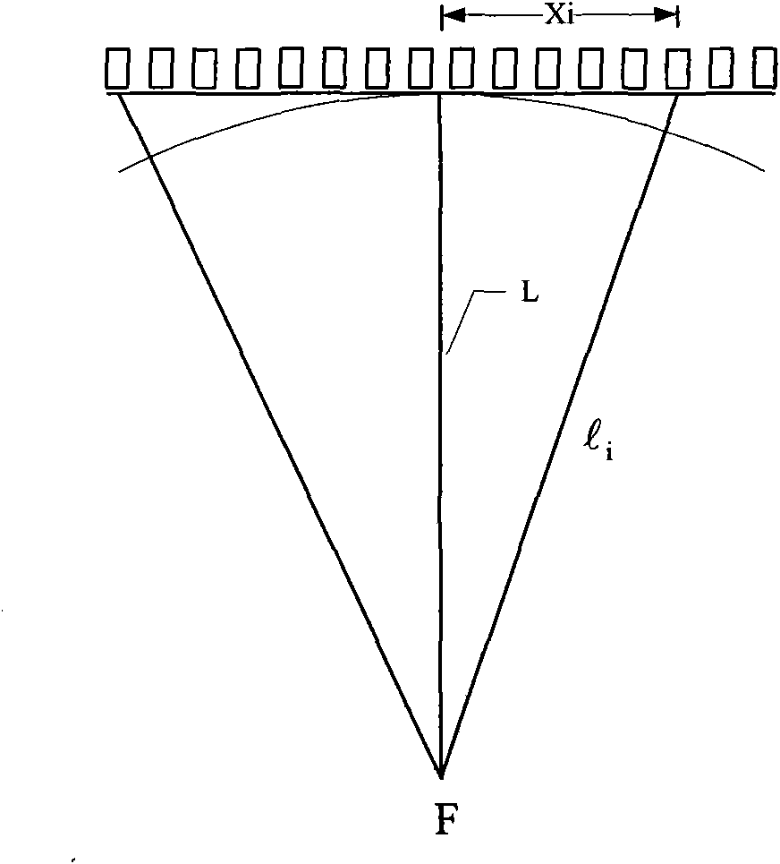
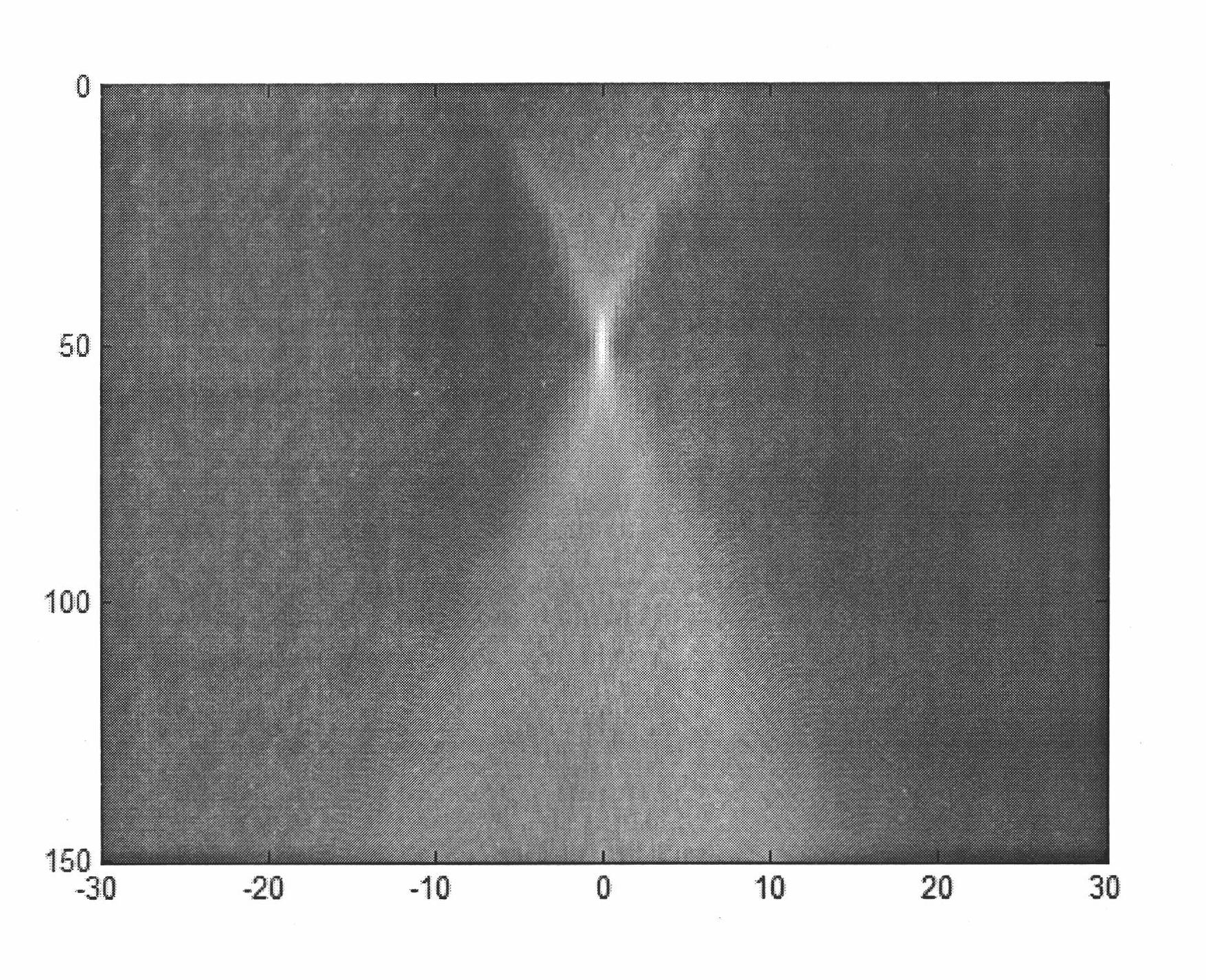
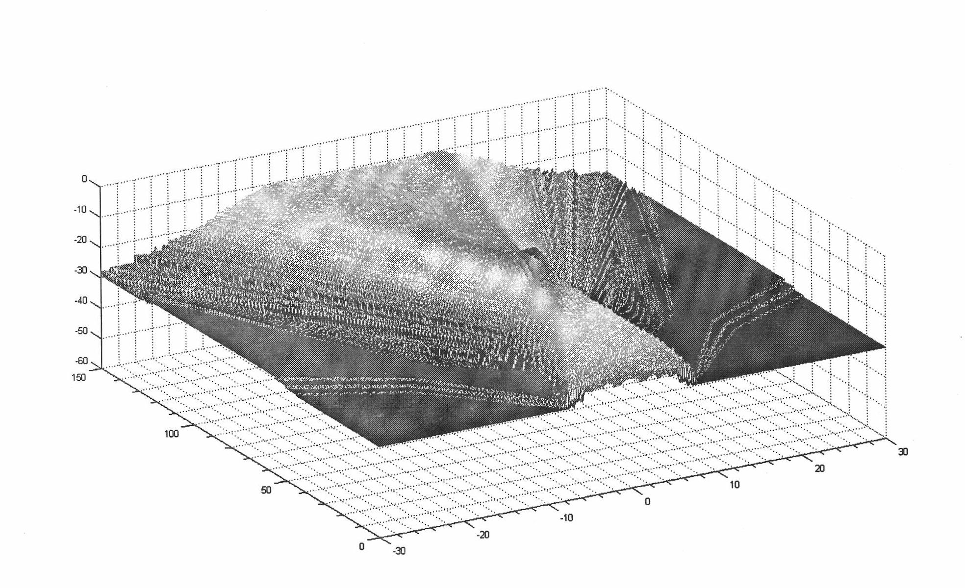
[0056] Example 1: A linear array ultrasonic probe with a center frequency of 7.5MHz, an aperture of 32 array elements, an array element spacing of 0.5mm, a total of 80 probe array elements, and a selection focus range of 0-100mm. The quantization unit of the transmission time delay is 0.015625 microseconds, (that is, the counting pulse of 64MHz), and the time delay calculated according to the formula (4) is quantized into the pulse period unit as shown in Figure 7 middle. The sound field distribution is as Figure 7 with Figure 8 shown.

example 2

[0057] Example 2: Convex array ultrasonic probe, center frequency 3.5MHz, number of aperture array elements 32, array element spacing 0.78, total number of probe array elements 128, use the general formula (5) to calculate the aspheric focusing delay of the convex array probe. The two parameters are: a=0.268, b=-1.54, the sound field distribution is as follows Figure 11 with Figure 12 shown.


PUM


Abstract

The invention discloses an aspheric focus method of using an ultrasonic probe to transmit pulse. The method comprises the following steps: A1. arranging M/2 focuses on the centre line of the acoustic propagation direction of the center bore of the ultrasonic probe, wherein M represents the array number of the transmitting aperture of the probe; A2, calculating the transmitting delay, corresponding to the center bore, of each array of the ultrasonic probe, wherein arrays are focused to the focuses; and A3, controlling the pulse transmitting sequence of each array of the ultrasonic probe according to the transmitting delay. The aspheric focus method of using the ultrasonic probe to transmit pulse focuses the transmitted pulse on a continuous area during primary emission, the sound field on every point of the scanning line within a certain range has better directivity and the flutter fading of the sound field distribution can not caused when the sound field is away the focuses, thus the ultrasound image has more uniform resolution and brightness.

Description

technical field [0001] The invention relates to the technical field of ultrasonic imaging, in particular to an aspherical focusing method for transmitting pulses by an ultrasonic probe. Background technique [0002] Modern ultrasound imaging systems basically use array transducers and electronic focusing technology. The electronic focusing of the ultrasound imaging system is divided into two aspects: transmitting focusing and receiving focusing. Since the signal can be buffered during the receiving process, point-by-point focusing can be achieved. Only one focal point can be selected for one launch during launch. The traditional electronic focusing method is to calculate the sound path length of each element of the array transducer to reach the focal point, and calculate the delay difference of each element from the sound path difference between each element. By controlling the pulse delay of each array element, the acoustic pulses of all array elements reach the focus at...

Claims


Application Information

Patent Timeline
IPC IPC(8): G01S15/89
Inventor 孟国海
Owner SHENZHEN LANDWIND IND
Why Eureka
Try Eureka