Optical engine for time-sharing work of P and S light

An optical engine and time-sharing technology, applied in the field of optical engines, can solve the problems of unfavorable brightness improvement and unfavorable light utilization rate of projector brightness improvement, and achieve the effects of comprehensive performance, improved light utilization rate, and improved brightness.

Inactive Publication Date: 2010-07-07
宁波市科技园区华域电子有限公司
View PDF1 Cites 23 Cited by
  • Summary
  • Abstract
  • Description
  • Claims
  • Application Information

AI Technical Summary

Problems solved by technology

[0002] In the projection system using LCD for image display, the traditional method is all in an LCD sheet, which can only pass P light or S light continuously, such as the technology disclosed in patent 200410081263.6. This method can only obtain a flat image. To obtain Stereoscopic images, then use two LCDs to pass through P light and S light respectively, and then synthesize stereoscopic images, or use two projectors with P light or S light output to synthesize images, such as figure 1 As shown, it is the traditional method of converting natural light into polarized light. Such a device will generally double its area during the process of converting natural light from the light source into polarized light, increasing the etendue of the light source, which will improve the brightness of the projector. and light utilization is extremely unfavorable
figure 1 The traditional method is to pass the light of a single light source, pass through the compound eye system composed of lenses 301 and 302, and then have PBS303 to convert polarized light, from figure 1 It can be seen that the P-S light is converted into S1 and S2 light, and the area of ​​the light source is doubled, which is extremely unfavorable for improving the brightness in the projection system, especially for light sources composed of surface light emitting elements such as LEDs and lasers.

Method used


Image

  • Optical engine for time-sharing work of P and S light
  • Optical engine for time-sharing work of P and S light
  • Optical engine for time-sharing work of P and S light

Examples


Embodiment Construction

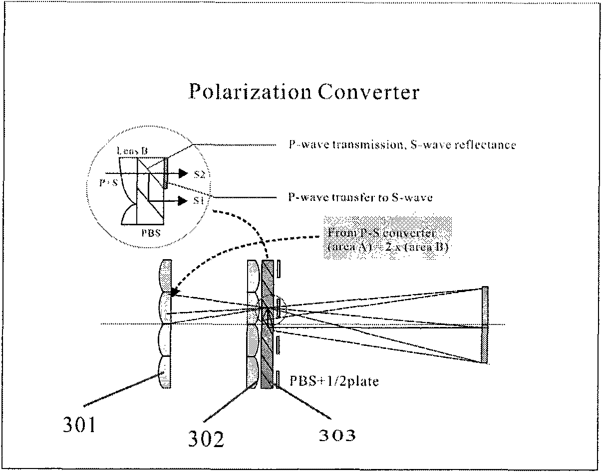
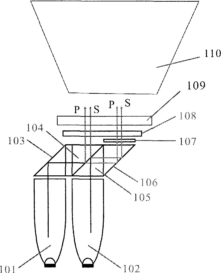
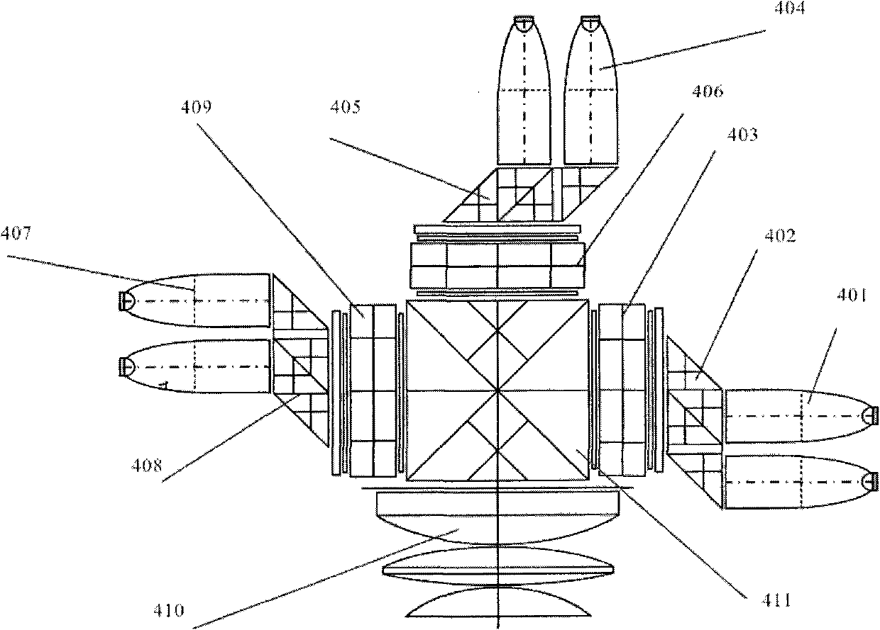
[0015] The present invention will be described in detail below in conjunction with accompanying drawing: figure 2 As shown, the present invention has at least two light sources, wherein at least one light source is converted into S light, and other light sources are converted into P light, and P light and S light enter the imaging LCD light valve modulator 108 in time division, and the imaging LCD light valve The modulator 108 makes the P light and the S light incident on the film inspector 109 through image processing, and can present the same plane or stereoscopic image.

[0016] The at least two light sources are converted elements 103, 104 and 105, 106 through at least two PBS conversion mechanisms, and the etendue after conversion remains unchanged, that is, the P light or S light emitted by the two light sources is Output within the same plane area. The at least two light sources include LED101, 102 or laser semiconductor light source or VHP or metal halide light sourc...


PUM


Abstract

The invention discloses an optical engine for time-sharing work of P and S light, which comprises at least two light sources, wherein at least one light source is converted into the S light, and the other light sources are converted into the P light. The S light and P light enter an imaging LCD light valve modulator in a time-sharing mode, and the imaging LCD light valve modulator makes the S light and P light pass through an analyzer by time-sharing incidence through image processing, and present the same plane or stereoscopic image. The at least two light sources pass through at least two conversion elements of a PBS converting mechanism and conversion elements, and the converted etendue is constant, namely, the P light or the S light emitted by the two light sources is input in the same plane area. The at least two light sources comprise an LED or a laser semiconductor light source or a VHP or a metal halide light source. The S light and the P light enter the imaging LCD light valve modulator in the time-sharing mode, pass through the analyzer by time-sharing incidence and can present the same plane or stereoscopic image. Therefore, the conversion loss of polarized light of the light sources is minimized, the lighting effect is improved, the slot time of the light sources can be utilized, the instantaneous power of the light sources is increased, and the optical output brightness is improved.

Description

technical field [0001] The invention relates to an optical engine, a modulator through which P and S light enter LCD light in a time-division manner, and an optical engine capable of presenting stereoscopic images, which belongs to the technical field of optical display. Background technique [0002] In the projection system using LCD for image display, the traditional method is all in an LCD sheet, which can only pass P light or S light continuously, such as the technology disclosed in patent 200410081263.6. This method can only obtain a flat image. To obtain Stereoscopic images, then use two LCDs to pass through P light and S light respectively, and then synthesize stereoscopic images, or use two projectors with P light or S light output to synthesize images, such as figure 1 As shown, it is the traditional method of converting natural light into polarized light. Such a device will generally double its area during the process of converting natural light from the light sour...

Claims


Application Information

Patent Timeline
Patent Type & Authority Applications(China)
IPC IPC(8): G03B21/14G02B27/18G02F1/13
Inventor 施振浩蔡铭
Owner 宁波市科技园区华域电子有限公司
Why Eureka
Try Eureka