Combined rotor structure of permanent-magnetic motor

A rotor structure, permanent magnet motor technology, applied in the direction of magnetic circuit shape/style/structure, magnetic circuit rotating parts, etc., can solve the problems of motor rotor strength deterioration, high processing defective rate, motor power loss, etc., to achieve increased The effect of large air gap magnetic field strength, improving efficiency and reducing magnetic flux leakage

Inactive Publication Date: 2010-07-07
LG ELECTRONICS (TIANJIN) APPLIANCES CO LTD
View PDF4 Cites 2 Cited by
  • Summary
  • Abstract
  • Description
  • Claims
  • Application Information

AI Technical Summary

Problems solved by technology

[0009] However, the embedded permanent magnet motor rotor of the prior art will produce a magnetic bridge phenomenon at the slot connection portion 39, causing magnetic flux leakage, resulting in loss of motor power, and at the slot connection portion 39, the strength of the motor rotor becomes worse, and the processing defect rate high

Method used


Image

  • Combined rotor structure of permanent-magnetic motor
  • Combined rotor structure of permanent-magnetic motor
  • Combined rotor structure of permanent-magnetic motor

Examples


Embodiment Construction

[0039] Hereinafter, the combined rotor structure of a permanent magnet motor of the present invention will be described in detail with reference to the accompanying drawings and embodiments:

[0040] In the drawings, the same symbols are used for the same components in the present invention as in the prior art.

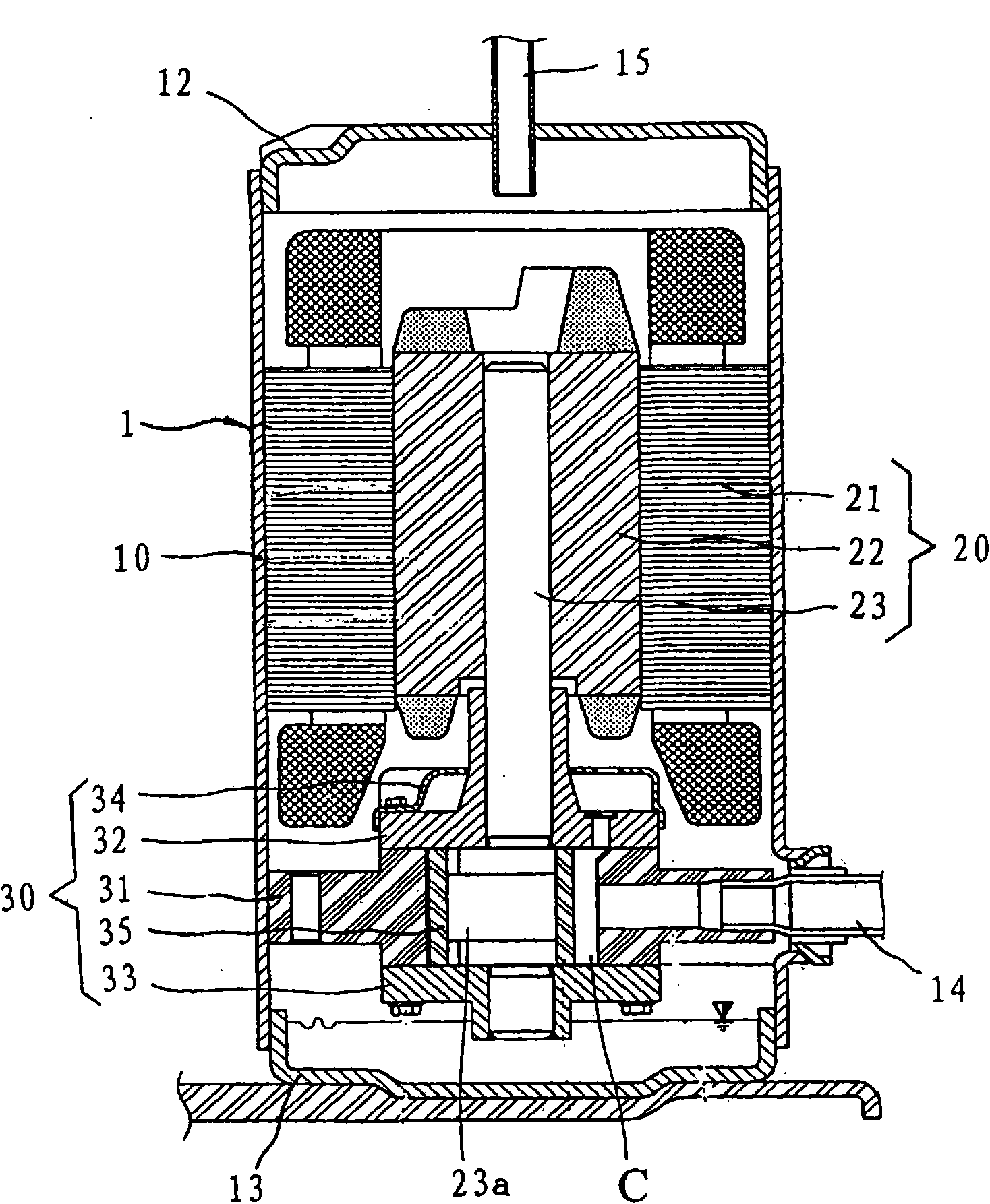
[0041] like Figure 1-7 As shown, a permanent magnet motor combined rotor structure, the motor assembly 20 is composed of a stator 21, a rotor 22, and a rotating crankshaft 23 that is pressed into the center of the rotor 22 and transmits rotational force.

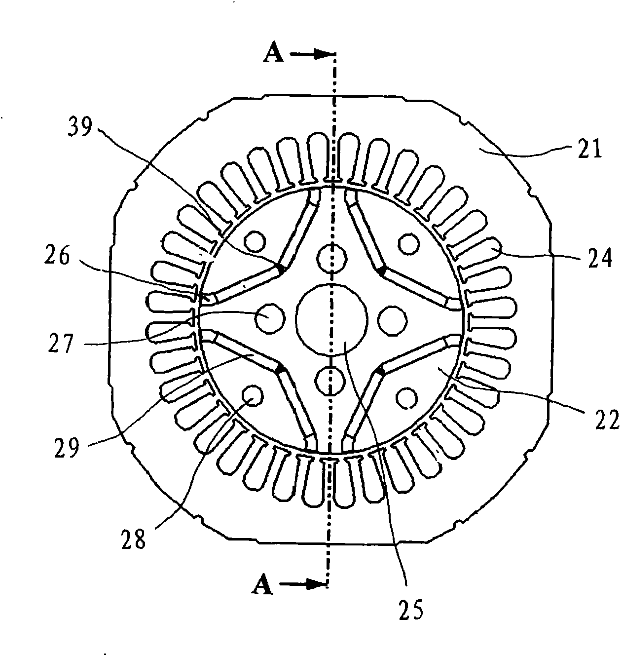
[0042] The stator 21 is composed of a stator core and a stator winding. The stator core is the main part of the main magnetic circuit. A plurality of slots 24 of the same shape are formed in the stator 21 for embedding the stator winding.

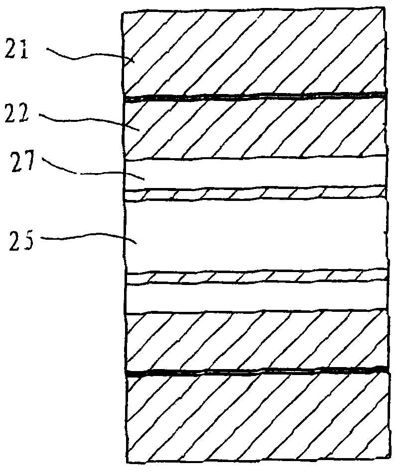
[0043] A plurality of permanent magnet slots 43 are formed on the rotor 40, and the plurality of permanent magnet slots 43 divide the rotor 40 into a rotor block 41 and a plura...


PUM


Abstract

The invention discloses a combined rotor structure of a permanent-magnetic motor. A combined rotor is composed by the assembling of a plurality of combination blocks. A plurality of combination-rotating holes and lightening holes are respectively formed on the rotor, a plurality of permanent magnets are respectively arranged on the rotor, and certain gaps are respectively arranged between two permanent magnets and at the other end of each permanent magnet. The plurality of combination blocks are combined together, the two ends of the combination blocks are clamped by clamping plates, and the combination blocks are connected together by balancing blocks and bolts through the combination-rotating holes so as to form the combined rotor. As the combined rotor structure is adopted and certain gaps are respectively arranged between two permanent magnets and at the other end of each permanent magnet, the magnetic leakage of the rotor is reduced, the intensity of an air-gap magnetic field is enhanced, the efficiency of the motor is increased, and processing materials of the rotor are saved as well.

Description

technical field [0001] The invention belongs to a motor, in particular to a combined rotor structure of a permanent magnet motor. Background technique [0002] Generally speaking, a motor is a machine that converts electrical energy into kinetic energy. Such a motor can be divided into a rotary motor that converts electrical energy into rotary motion and a reciprocating motor that converts electrical energy into linear reciprocating motion. [0003] The working principle of the single-phase induction motor is: after electrification, electromagnetic induction is generated between the stator and the rotor, and the rotor rotates to realize the conversion of electrical energy into mechanical energy. Motors for compressors are installed as power sources in household appliances such as refrigerators and air conditioners. [0004] like Figure 1~2 As shown, the compressor in the prior art includes a casing 1, a motor assembly 20 is installed on the inner upper side of the casing 1...

Claims


Application Information

Patent Timeline
Patent Type & Authority Applications(China)
IPC IPC(8): H02K1/27
Inventor 于涛
Owner LG ELECTRONICS (TIANJIN) APPLIANCES CO LTD
Why Eureka
Try Eureka