
Equipment for measuring intra-ocular pressure and method for measuring intra-ocular pressure using same

An intraocular pressure and equipment technology, applied in the direction of tonometer, etc., can solve the problems of long acceleration time of probe movement speed, inability to fully guarantee the speed, and impact on the corneal surface, etc. The effect of high system efficiency

Inactive Publication Date: 2010-07-14
TIANJIN SUOWEI ELECTRONICS TECH
View PDF4 Cites 11 Cited by
  • Summary
  • Abstract
  • Description
  • Claims
  • Application Information

AI Technical Summary

Problems solved by technology

[0006] The problem with its technical solution is that the acceleration time of the probe movement speed is too long, the distance between the rear part of the probe and the transmitting coil affects the probe speed, and the probe cannot guarantee a long enough high-speed uniform motion. In order to ensure a long enough high-speed uniform motion Time must reduce efficiency to increase driving force, cannot sufficiently guarantee high enough velocity to hit corneal surface

Method used


Image

  • Equipment for measuring intra-ocular pressure and method for measuring intra-ocular pressure using same
  • Equipment for measuring intra-ocular pressure and method for measuring intra-ocular pressure using same
  • Equipment for measuring intra-ocular pressure and method for measuring intra-ocular pressure using same

Examples


Embodiment Construction

[0028] Referring to the accompanying drawings, the technical solution of the present invention is described in detail in conjunction with two embodiments:

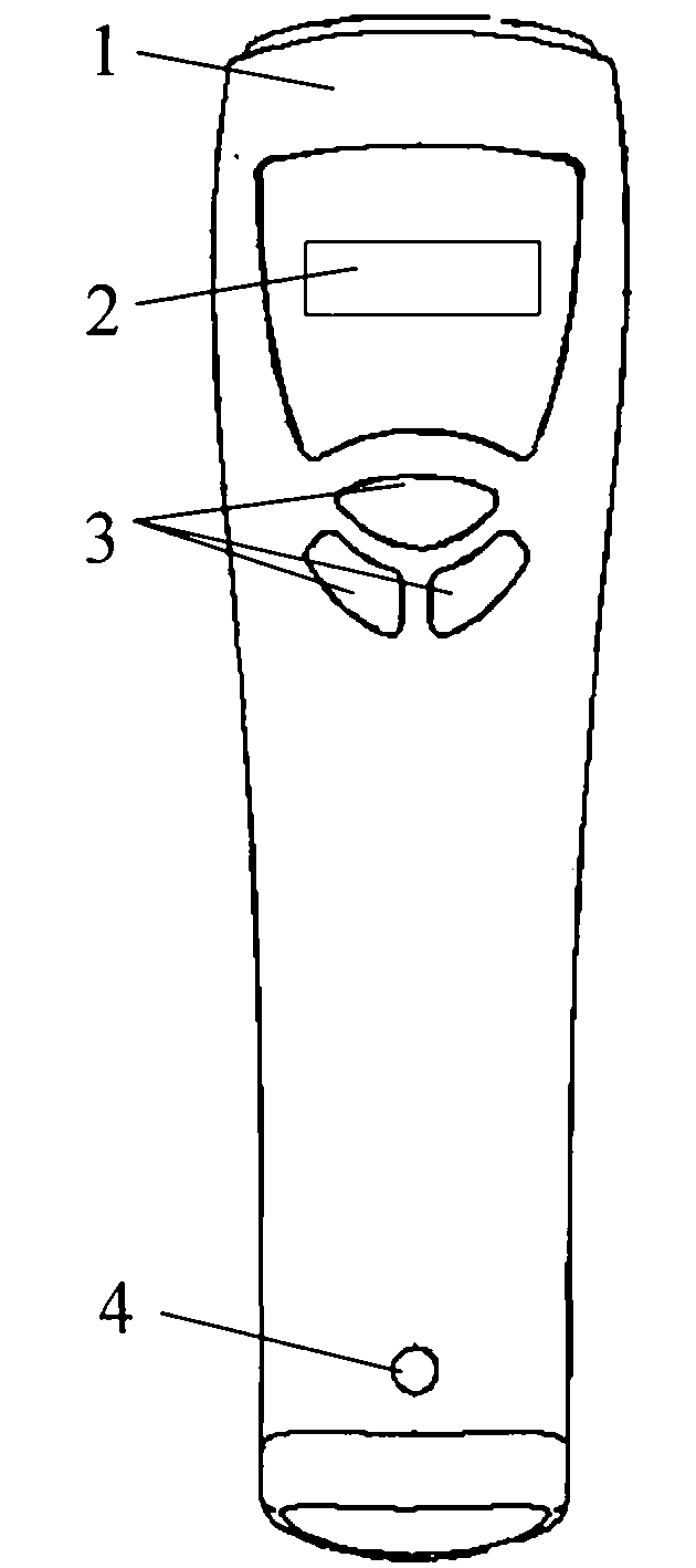
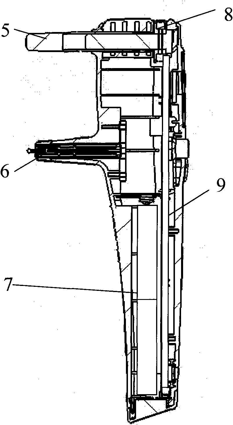
[0029] as attached figure 1 and attached figure 2 , the LCD screen (2) is fixed on the circuit board (9), the circuit board (9), the measurement and setting button (3), the power button (4), the forehead support (5), the probe drive assembly (6), The battery (7) and the regulating wheel (8) are all mounted on the fixed casing (1).

[0030] During measurement, usually the front end of the forehead support (5) is against the forehead of the subject, and the adjustment wheel (8) can be turned to make the forehead support extend or shorten, thereby adjusting the probe head in the probe drive assembly and the front surface of the cornea. When the distance reaches the appropriate range (generally 4-9mm), press the measurement button, the probe will launch, and the LCD will display the measurement result after the measurement ...


PUM


Abstract

The invention relates to equipment for measuring intra-ocular pressure, which is mainly characterized by comprising a probe supported in a probe shoulder, a plurality of coils wound on a framework, and a circuit board for collecting and processing voltage signals of the coils. The probe consists of a plastic probe head and a magnetic probe tail, and the probe tail consists of one or several joints of magnetic needles. The equipment for measuring the intra-ocular pressure is mainly characterized in that the coils are electrified with different directions to drive the magnetic needles at the probe tail to ensure part of the probe head to move toward or far away from a cornea at a high speed, and the intra-ocular pressure is figured out by the time interval between the probe closing to the cornea and the probe just leaving the cornea. By adopting the technical scheme of the invention, the speed-up time of the probe is shortened, the retention time of high speed motion is long, and the system efficiency is high, thereby fully ensuring that the probe can hit against the surface of the cornea at a speed high enough, greatly reducing the complexity and cost of the system, and simultaneously improving the reliability of the system.

Description

technical field [0001] The present invention relates to a device for measuring intraocular pressure and a method for measuring intraocular pressure with the device. Background technique [0002] Intraocular pressure is formed by the pressure exerted by the contents of the eyeball (aqueous humor, crystal, vitreous body, etc.) necessary diagnostic tool. [0003] At present, the commonly used equipment for detecting intraocular pressure is divided into two types in principle: one is indentation type, such as The principle of the tonometer is to use an indenter with a certain force to press the front surface of the cornea to measure the indentation depth of the cornea to indirectly determine the intraocular pressure; the other is the applanation type, and its principle is to measure the specific corneal surface area, including Goldmann tonometers as well as non-contact pneumatic tonometers. [0004] The above-mentioned method for measuring intraocular pressure has a complica...

Claims


Application Information

Patent Timeline
Patent Type & Authority Applications(China)
IPC IPC(8): A61B3/16
Inventor 石俊山王健发王雪乔
Owner TIANJIN SUOWEI ELECTRONICS TECH
Learn More