Reciprocating shaft magnetic liquid sealing structure

A technology of magnetic liquid and sealing structure, which is applied in the direction of engine sealing, engine components, mechanical equipment, etc., can solve the problems of sealing life and sealing pressure reduction, increase of sealing medium leakage rate, loss of magnetic liquid, etc., to improve sealing life and the effect of sealing and pressure resistance

Inactive Publication Date: 2010-07-14
BEIJING JIAOTONG UNIV
View PDF5 Cites 18 Cited by
  • Summary
  • Abstract
  • Description
  • Claims
  • Application Information

AI Technical Summary

Problems solved by technology

[0002] In the existing reciprocating shaft magnetic liquid seal, when the reciprocating shaft moves at a certain speed and stroke, the magnetic liquid under the sealing teeth is deformed, and the magnetic liquid on each sealing tooth will be brought to the furthest point in the moving direction of the reciprocating shaft. In this way, when the magnetic field under the front sealing teeth is not enough to bind the excess magnetic liquid, a considerable amount of magnetic liquid will be lost, resulting in a decrease in seal life and seal pressure, and the sealed medium Increased leak rate

Method used


Image

  • Reciprocating shaft magnetic liquid sealing structure
  • Reciprocating shaft magnetic liquid sealing structure
  • Reciprocating shaft magnetic liquid sealing structure

Examples


Embodiment approach 1

[0022] A reciprocating shaft magnetic liquid sealing structure, the structure includes: a first bearing 4, a first magnetic isolation ring 6, a first pole piece 7, a first O-shaped rubber seal ring 8, a permanent magnet 10, a second O-shaped rubber seal The ring 12, the second pole shoe 13, the second magnetic isolation ring 14, and the second bearing 16 are close to the inner boss of the outer casing 3 in turn, and the end cover 18 is fixed on the outer casing 3 with screws 17, and the second bearing 16 is pressed tightly. ; When in use, inject magnetic liquid into the inner ring surface of the permanent magnet 10, and install the above-mentioned sealing structure on the reciprocating shaft 1 plated with polytetrafluoroethylene 5.

[0023] The first bearing 4 and the second bearing 16 adopt linear bearings of the same type.

[0024] The structure of the first pole piece 7 and the second pole piece 13 are exactly the same.

[0025] The inner ring surface of the first pole sho...

Embodiment approach 2

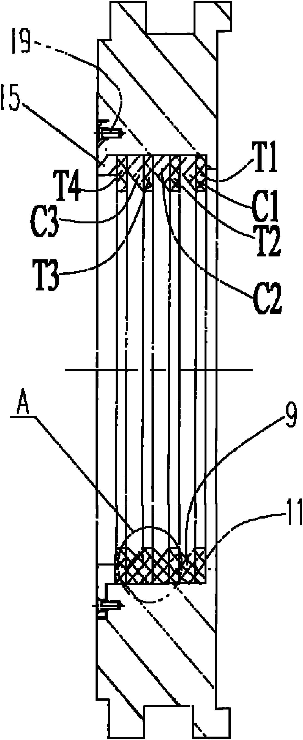
[0028] The difference from Embodiment 1 is that the first elastic ring T1, the first trapezoidal seal teeth C1, the second elastic ring T2, and the second trapezoidal seal are closely spaced in the middle stepped hole on the inner ring surface of the second pole piece 13. Tooth C2, third elastic ring T3, third trapezoidal sealing tooth C3 and fourth elastic ring T4, see figure 2 .

Embodiment approach 3

[0030] The difference from Embodiment 1 is that the first elastic ring T1, the first trapezoidal seal tooth C1, the second elastic ring T2, ..., the The seventh trapezoidal sealing tooth C7, the eighth elastic ring T8, the eighth trapezoidal sealing tooth C8, the ninth elastic ring T9, see Figure 7 , 8 .

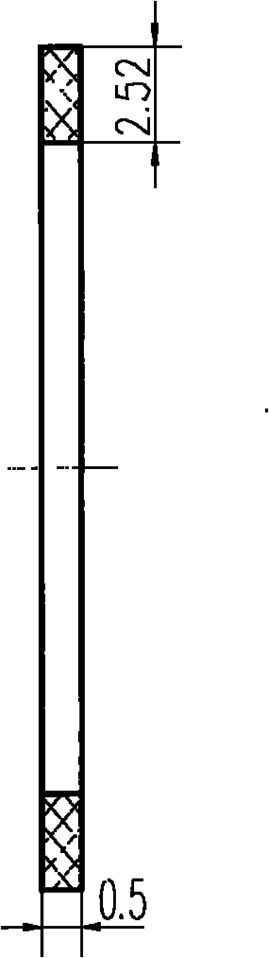
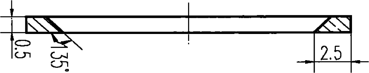
[0031] The tooth shape parameters of the trapezoidal sealing tooth C described in the embodiment are: tooth height 2.5mm, tooth width 0.5mm, inclination angle 45 degrees, see Figure 5 ; The thickness of the elastic ring is 0.5mm, and the difference between the inner and outer diameters is 2.52mm, see Figure 4 .

[0032] On the surface of the reciprocating shaft 1 described in the embodiment, a groove with a depth of 0.1mm is machined, the axial length of the groove is greater than or equal to 4×(thickness of all trapezoidal seal teeth+thickness of all elastic rings), in the groove A polytetrafluoroethylene film 5 with a thickness of 0.1mm is coated in the tank. Due t...


PUM


Abstract

The invention relates to a reciprocating shaft magnetic liquid sealing structure, which comprises a first bearing, a first magnetic-isolated ring, a first pole piece, a first O-shaped rubber gasket ring, a permanent magnet, a second O-shaped rubber gasket ring, a second pole piece, a second magnetic-isolated ring and a second bearing, which are sequentially and closely propped against an external nested inner lug boss, wherein an end cover is fixed on an outer jacket through a bolt, and the second bearing is compressed. The inner annular surface of the second pole piece (13) is provided with a left, a middle and a right counter bores, elastic rings (T) with the quantity of N+1 and trapezoid sealing gears (C) are arranged at intervals from each other to be closely arranged inside the middle counter bore, N is a positive integer of 1 to 8, the trapezoid sealing gears and the elastic rings, which are closely lined at intervals, are fixedly connected with the second pole piece in a threading way through bolts and retainer rings (15), and the trapezoid sealing gears with the quantity of N are lined up in the expansion direction of the identical inner holes; and the structure of the first pole piece (7) is completely identical to that of the second pole piece. The problems of the conventional reciprocating shaft magnetic liquid sealing structure that the magnetic liquid runs off, the sealing service life is shortened, and the leakage rate is increased can be solved.

Description

technical field [0001] The invention belongs to the technical field of mechanical engineering seals, and is particularly suitable for the seals of reciprocating shafts. Background technique [0002] In the existing reciprocating shaft magnetic liquid seal, when the reciprocating shaft moves at a certain speed and stroke, the magnetic liquid under the sealing teeth is deformed, and the magnetic liquid on each sealing tooth will be brought to the furthest point in the moving direction of the reciprocating shaft. In this way, when the magnetic field under the front sealing teeth is not enough to bind the excess magnetic liquid, a considerable amount of magnetic liquid will be lost, resulting in a decrease in seal life and seal pressure, and the sealed medium Increased leak rate. Contents of the invention [0003] The technical problem to be solved by the present invention is that the loss of the magnetic fluid caused by the existing reciprocating shaft magnetic fluid sealing...

Claims


Application Information

Patent Timeline
Patent Type & Authority Applications(China)
IPC IPC(8): F16J15/43
CPCF16J15/43F16C33/763
Inventor 李德才杨文明
Owner BEIJING JIAOTONG UNIV
Why Eureka
Try Eureka