Large single-stage rubber diaphragm-sealed accumulator unit

A gas storage device and rubber sealing technology, which is applied in the field of gas storage cabinets, can solve problems such as unstable operation parameters of pressurizers, troublesome operation and maintenance of gas cabinets, unstable pressure of gas cabinets, etc., and achieve good results. Economic benefits, reduced maintenance work, and stable gas storage pressure

Active Publication Date: 2010-07-14
MCC CAPITAL ENGINEERING & RESEARCH
View PDF2 Cites 13 Cited by
  • Summary
  • Abstract
  • Description
  • Claims
  • Application Information

AI Technical Summary

Problems solved by technology

The two-stage seal also has two gas storage pressures, that is, one pressure when the piston rises, and one pressure when the piston drives the T-shaped baffle to rise, which makes the pressure of the gas tank unstable, resulting in the operation of the subsequent pressurizer. Instability of user parameters
In addition, when the gas storage capacity reaches the upper half of the two-stage rubber membrane sealed gas cabinet, the piston drives the T-shaped baffle to move up and down; when the gas storage capacity reaches the lower half, the T baffle falls on the lower bracket , the piston drives the T-shaped baffle to run up and down by its top impact head, so the T-shaped baffle will inevitably shift or rotate after repeated operations, which will bring troubles to the safe operation and maintenance of the gas cabinet
In view of the fact that the existing gas storage device is difficult to meet the requirements of metallurgical users with large gas storage capacity, stable gas storage pressure, simple operation and use, and small maintenance, the present invention proposes a large-capacity single-stage rubber-membrane-sealed gas storage device

Method used


Image

  • Large single-stage rubber diaphragm-sealed accumulator unit
  • Large single-stage rubber diaphragm-sealed accumulator unit
  • Large single-stage rubber diaphragm-sealed accumulator unit

Examples


Embodiment Construction

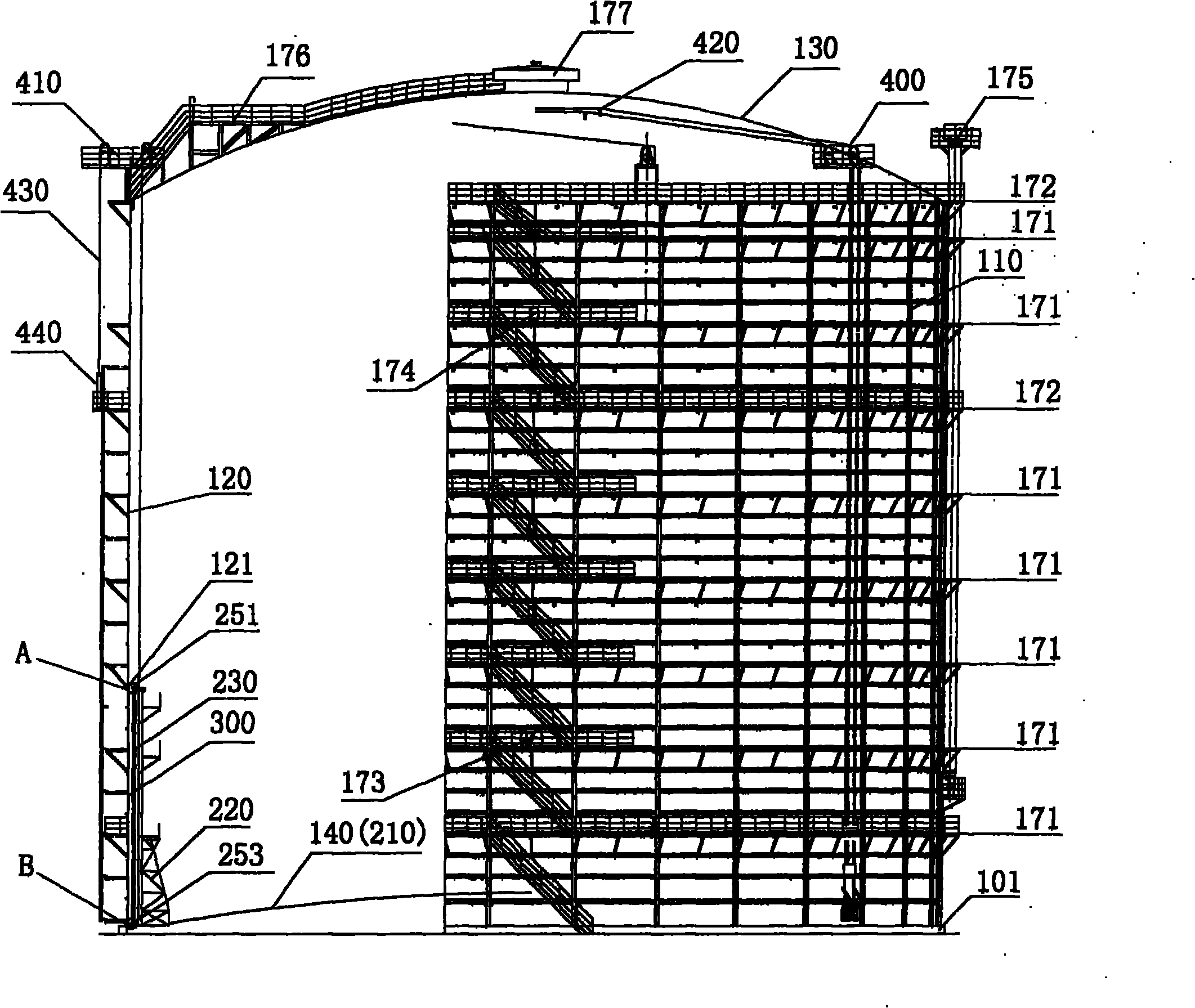
[0037] The specific implementation manner of the present invention will be further described in detail below in conjunction with the drawings and specific examples.

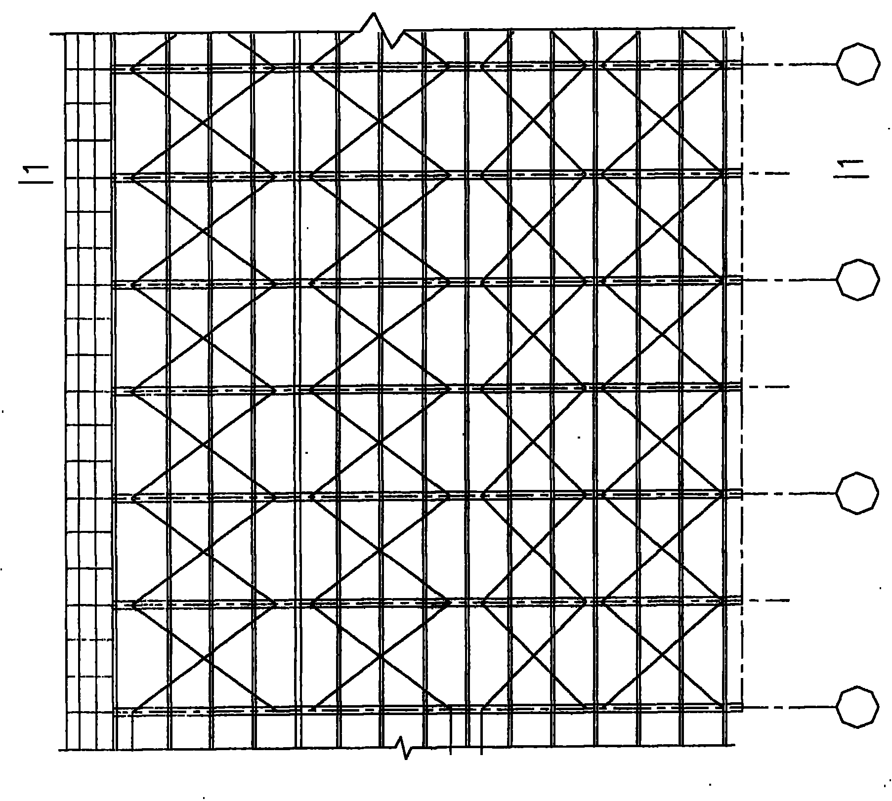
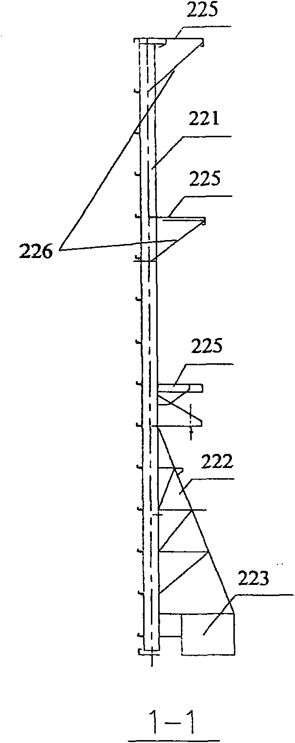
[0038] As shown in the figure, the present invention proposes a large-scale single-stage rubber-membrane-sealed gas storage device. The gas storage device includes a cabinet, a piston, and a sealing film forming a seal between them. The cabinet includes a column, The side plate, the cabinet top plate and the cabinet bottom plate form a cylindrical shell; the inside of the cabinet is provided with a piston that can rise and fall freely, and the rubber sealing film is arranged between the outside of the piston and the side plate of the cabinet, and the The lower edge of the rubber sealing film is connected to the lower part of the piston, and the upper edge is fixed to the inner wall of the side plate of the cabinet to form a single-stage sealed gas storage device; the side plate of the cabinet, the rubber sealing f...


PUM


Abstract

The invention discloses a large single-stage rubber diaphragm-sealed accumulator unit. The accumulator unit comprises a cabinet body, a piston and a seal diaphragm for sealing the cabinet body and the piston, wherein the cabinet body comprises an upright post, a side plate, a top cabinet plate and a bottom cabinet plate which form a cylindrical shell; the piston which can rise and fall freely is arranged in the cabinet body, the rubber seal diaphragm is arranged between the outer side of the piston and a side cabinet plate, the lower edge of the rubber seal diaphragm is connected with the lower part of the piston, and the upper edge is fixed to the inner wall of the side cabinet plate to form the single-stage sealed accumulator unit; and the side cabinet plate, the rubber seal diaphragm, the piston and the bottom cabinet plate form a sealed barrel, and the piston drives the rubber seal diaphragm to move up and down in the cabinet body to store and release coal gas. By using the accumulator unit, the compressor can run stably and reliably and can provide the coal gas for users in the more stable pressure.

Description

technical field [0001] The invention relates to a gas storage cabinet, in particular to a large single-section rubber membrane-sealed gas storage device used in the metallurgical industry. Background technique [0002] Due to the large capacity of the two-stage sealed gas storage, the rubber membrane-sealed gas cabinets currently used in the metallurgical industry in China are mainly two-stage sealed structures, and their maximum capacity can reach 150,000m 3 or larger. The two-stage seal also has two gas storage pressures, that is, one pressure when the piston rises, and one pressure when the piston drives the T-shaped baffle to rise, which makes the pressure of the gas tank unstable, resulting in the operation of the subsequent pressurizer. Instability of user parameters. In addition, when the gas storage capacity reaches the upper half of the two-stage rubber membrane sealed gas cabinet, the piston drives the T-shaped baffle to move up and down; when the gas storage cap...

Claims


Application Information

Patent Timeline
Patent Type & Authority Applications(China)
IPC IPC(8): F17B1/013F17B1/04
Inventor 包儒涵杨永柴凤飞孙鹉翎刘红娟曹宝平王骏涛李巍王世芹杨光
Owner MCC CAPITAL ENGINEERING & RESEARCH
Why Eureka
Try Eureka