Heat exchanger

A heat exchanger and multi-group heat dissipation technology, applied in the field of heat exchange, can solve problems such as unreliable welding, high welding plugging of products, and increased manufacturing costs, and achieve the effects of stable heat conduction efficiency, convenient manufacturing and processing, and improved pass rate

Active Publication Date: 2010-07-14
SANHUA HANGZHOU MICRO CHANNEL HEAT EXCHANGER
View PDF0 Cites 8 Cited by
  • Summary
  • Abstract
  • Description
  • Claims
  • Application Information

AI Technical Summary

Problems solved by technology

[0007] In the welding process, since the two ends of the heat dissipation flat tube 3 are inserted into the collecting pipe, and the partition plate 6 and the end cover 7 also extend into the inner cavity of the collecting pipe, the heat dissipation flat pipe 3, the partition plate 6 and the end cover 7 Welding with headers 1 and 2 will be more reliable, but since the contact between the fins and the heat-dissipating flat tubes is only a few lines, sometimes some fins will fall off during or after welding, especially for some large At this time, some heat exchangers are fixed by sticking, and some are fixed by welding after the second furnace welding. In the second welding,

Method used


Image

  • Heat exchanger
  • Heat exchanger
  • Heat exchanger

Examples


Embodiment Construction

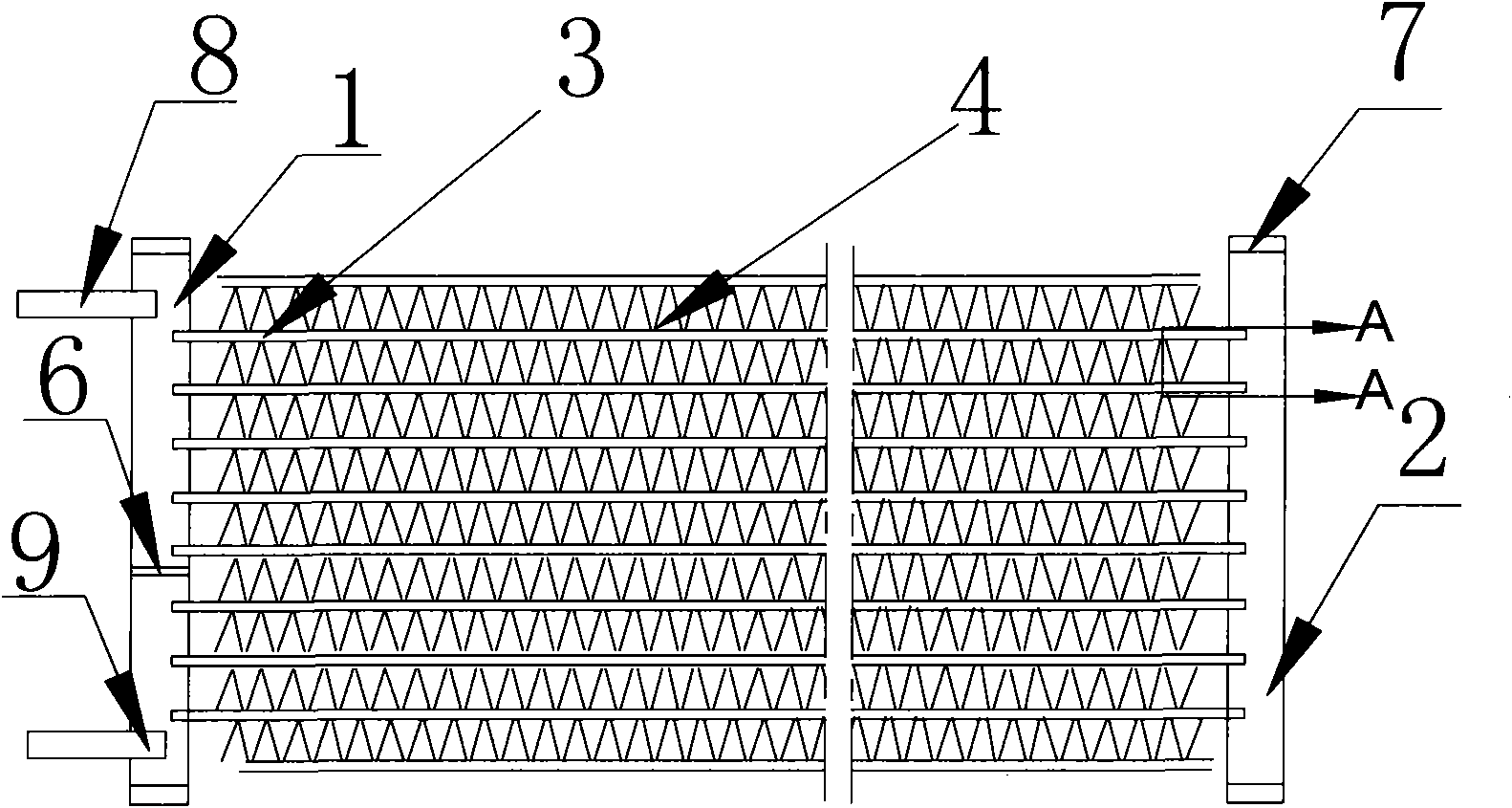
[0041] The core of the present invention is to provide a heat exchanger that can effectively fix the heat dissipation flat tubes and fins so that the heat transfer effect of the heat exchanger is relatively stable and reliable, the reliable life is long, and the pass rate of the manufacturing process is improved without increasing the difficulty of manufacturing and processing. .

[0042] In order to enable those skilled in the art to better understand the solution of the present invention, the present invention will be further described in detail below in conjunction with the accompanying drawings and embodiments. Since the heat exchanger is a well-known technology, the same parts as the prior art will not be repeated here, but only the differences from the prior art will be introduced.

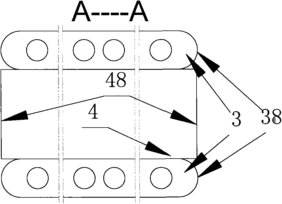
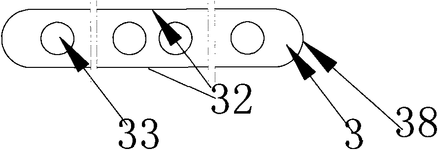
[0043] The heat exchanger generally includes headers 1 and 2 arranged on both sides of the heat exchanger, multiple sets of heat dissipation flat tubes connected to the header through the in...


PUM


Abstract

The invention discloses a heat exchanger comprising a first collecting pipe, a second collecting pipe and a plurality of sets of radiation flat pipes arranged between the first collecting pipe and the second collecting pipe. Ports in which the radiation flat pipes can be inserted are arranged at one sides of the collecting pipes. The radiation flat pipes are inserted into the collecting pipes through the ports. Fins used for heat radiation are arranged between adjacent two sets of radiation flat pipes. Positioning mechanisms for preventing the horizontal movement of the fins are arranged between the radiation flat pipes and the fins. After the use of the positioning mechanisms, the radiation flat pipes and the fins of the heat exchanger can be stably and reliably positioned, and the service life of the heat exchanger can be prolonged. The positioning mechanisms are more suitable for heat exchangers with fins wider than radiation flat pipes. The disconnection caused by the collision of the fins with other components during the assembly, as well as other problems, can be avoided, thereby improving the heat exchange efficiency of the heat exchanger.

Description

technical field [0001] The invention relates to the technical field of heat exchange, in particular to a parallel flow heat exchanger. Background technique [0002] A heat exchanger is a device that realizes heat transfer between cold and hot fluids, and is widely used in HVAC and other fields. Please refer to the attached picture, figure 1 It is a structural schematic diagram of a heat exchanger in the prior art, figure 2 for figure 1 A-A view of the, Figure 2a then figure 2 The transverse front view of the heat dissipation flat tube, Figure 2b for figure 2 Front view of the fin in, Figure 2c for figure 2 Side view of the fin in . [0003] A heat exchanger in the prior art generally includes a header 1 and a header 2 parallel to each other, and the two can usually be arranged parallel to each other, and there are a plurality of heat-dissipating flat tubes 3 that are generally arranged in parallel between the two. Fins 4 for fixed heat dissipation are provid...

Claims


Application Information

Patent Timeline
IPC IPC(8): F28D1/053F28F9/26
Inventor 董长盛
Owner SANHUA HANGZHOU MICRO CHANNEL HEAT EXCHANGER
Why Eureka
Try Eureka