Fault positioning method for transmission line

A fault location and transmission line technology, applied in the field of power system, can solve the problems of reducing the reliability of positioning, not considering the real-time wave velocity measurement at the moment of the fault, affecting the accuracy of fault location, and achieving the effect of ensuring reliability and accuracy.

Inactive Publication Date: 2010-07-14
SHANGHAI JIAO TONG UNIV
View PDF0 Cites 61 Cited by
  • Summary
  • Abstract
  • Description
  • Claims
  • Application Information

AI Technical Summary

Problems solved by technology

At present, using the high-precision clock function of GPS and wavelet transform analysis technology, the arrival time of the traveling wave head can be accurately determined in theory, but due to the limitation of the frequency band of the traditional transformer, there are still large errors in the measurement of the traveling wave head
For the problem of determining the velocity of traveling waves, in addition to estimating line parameters or directly applying traditional methods such as reference values ​​and empirical values, scholars at home and abroad have also proposed various solutions, such as: using the fault outside the area to determine the velocity of traveling waves The distance measurement method influenced by the wave velocity, etc., but these methods do not consider the real-time wave velocity measurement problem at the moment of the fault
Since there are many factors affecting the traveling wave velocity, if the real-time traveling wave velocity cannot be accurately calculated, the accuracy of fault location will be affected and the reliability of positioning will be reduced
[0004] After searching the existing literature, it was found that "Coal Mine Electromechanical" published an article entitled "Research on Transmission Line Fault Location Based on Traveling Wave Method" in the fifth issue of 2004 (p69-72). A double-terminal ranging method that installs a traveling wave detection device on the low-voltage side. This method directly uses the speed of light as the traveling wave velocity, but this technology is limited by the frequency band of the traditional transformer, so the ranging accuracy is not high, and the measurement error is 0.367%.

Method used


Image

  • Fault positioning method for transmission line
  • Fault positioning method for transmission line
  • Fault positioning method for transmission line

Examples


Embodiment

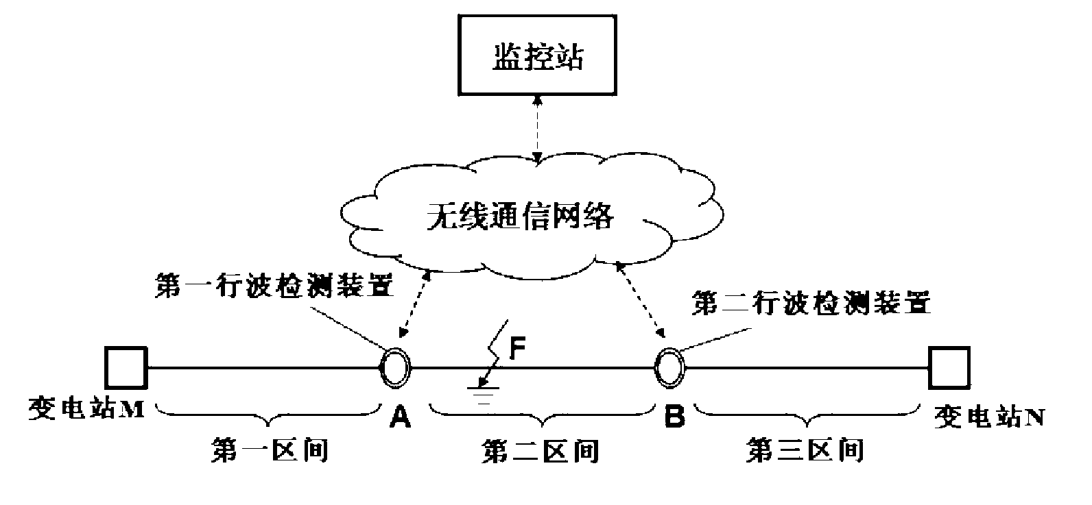
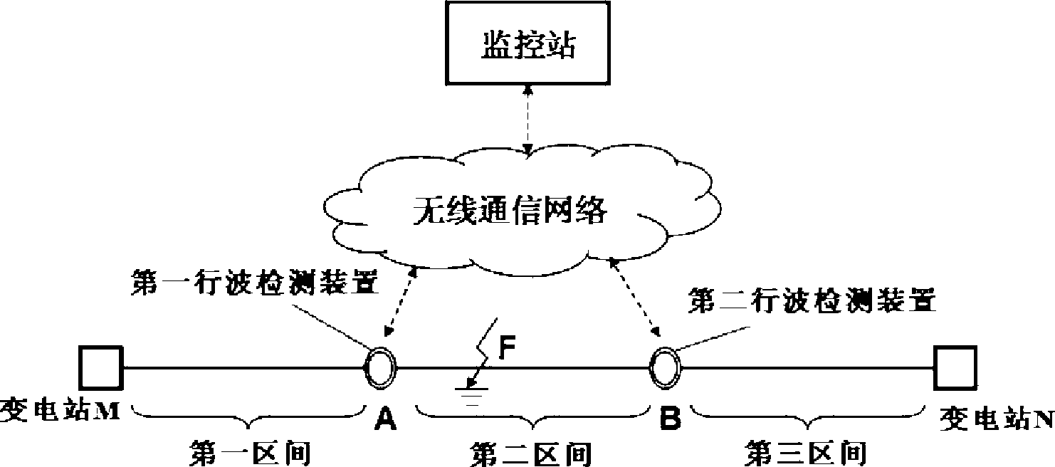
[0036] This embodiment is used to carry out fault distance measurement to a 150km high-voltage transmission line, including the following steps:

[0037] first step, such as figure 1 As shown, the high-voltage transmission line between the adjacent substation M and substation N is 150km long. Taking the busbar of substation M as the reference end, the detection point A and the detection point are respectively set up on the transmission line at 50km and 100km away from the reference end. B. The first set of Rogowski coil-based broadband core-through traveling wave detection device is installed on detection point A, and the second set of Rogowski coil-based broadband core-through type traveling wave detection device is installed on detection point B. Substation M and detection point A The section in between is the first section, the section between detection point A and detection point B is the second section, and the section between detection point B and substation N is the thi...


PUM


Abstract

The invention discloses a fault positioning method for a transmission line and belongs to the technical field of power systems. The fault positioning method comprises the following steps: arranging a Rogowski coil-based broadband core-through traveling wave detection device on the high-voltage transmission line; acquiring a current traveling wave signal of a three-phase line; performing singular value detection by applying the phase mode conversion and wavelet mode maximum principle; accurately identifying the traveling wave line mode wave head, and accurately determining the wave head arrival time by using a GPS high-precision clock; and measuring the wave speed of real-time traveling wave mode on line according to different wave head time difference information to realize accurate fault positioning. The fault positioning method has the advantages of effectively avoiding two main factors influencing the traveling wave fault positioning precision, along with high positioning precision and accurate and reliable fault positioning result.

Description

technical field [0001] The invention relates to a method in the technical field of electric power systems, in particular to a fault distance measurement method for transmission lines. Background technique [0002] After a fault occurs on a high-voltage transmission line, a transient traveling wave running to both ends will be generated at the fault point. When the transient traveling wave encounters an inhomogeneous medium during propagation, refraction and reflection will occur. Using the fault information contained in the transient traveling wave, theoretically accurate fault location can be achieved. Scholars and experts at home and abroad have done a lot of research on traveling wave ranging technology. By installing traveling wave detection devices on the secondary side (low voltage side) of voltage and current transformers in substations, various methods based on single-ended or double-ended methods can be used. This positioning algorithm completes fault distance meas...

Claims


Application Information

Patent Timeline
Patent Type & Authority Applications(China)
IPC IPC(8): G01R31/08
Inventor 盛戈皞徐湘忆刘亚东江秀臣邵庆祝
Owner SHANGHAI JIAO TONG UNIV
Why Eureka
Try Eureka