
Movement control servo loop device

A technology of motion control and motion position, applied in the direction of electric controllers, controllers with specific characteristics, etc., can solve the problem of slowing down the response speed, failing to respond to the system, correcting steady-state error control performance, affecting the tracking accuracy of the control system, and Trajectory accuracy and other issues

Active Publication Date: 2010-07-14
IND TECH RES INST
View PDF0 Cites 11 Cited by
  • Summary
  • Abstract
  • Description
  • Claims
  • Application Information

AI Technical Summary

Problems solved by technology

[0003] The aforementioned open-loop control is controlled by the internal pulse generator of the controller directly outputting position commands. There is no feedback signal for system comparison and error calculation, and it is impossible to correct the control performance such as system response speed and steady-state error. It is only suitable for low precision control occasions
[0004] The proportional-integral-derivative control loop has a proportional, integral, differential and feed-forward controller structure. The controller can differentiate the error amount with respect to time, which can improve the transient response ability, while the integral controller can perform integral and cumulative calculation on the error amount, and when the system tends to a steady state, the influence of the integral term will be enlarged with time , to eliminate the steady-state error. However, although the integral control loop can eliminate the steady-state error, it will slow down the response speed and cannot react immediately to the instantaneous changes of the system. If the integral term gain and integral time parameters are set too large, it is easy to The steep rise causes the controlled body of the system to oscillate and be in an unstable state, and the servo lags behind under high-speed control, resulting in a response delay phenomenon, which affects the tracking accuracy and trajectory accuracy of the control system, which is not conducive to high-precision control

Method used


Image

  • Movement control servo loop device
  • Movement control servo loop device
  • Movement control servo loop device

Examples


Embodiment Construction

[0037] The technical means and effects used by the present invention to achieve the technical purpose will be described below with reference to the accompanying drawings. The embodiments listed in the accompanying drawings are only for auxiliary illustration, but the technical means of the present invention are not limited to the listed appended drawings. picture.

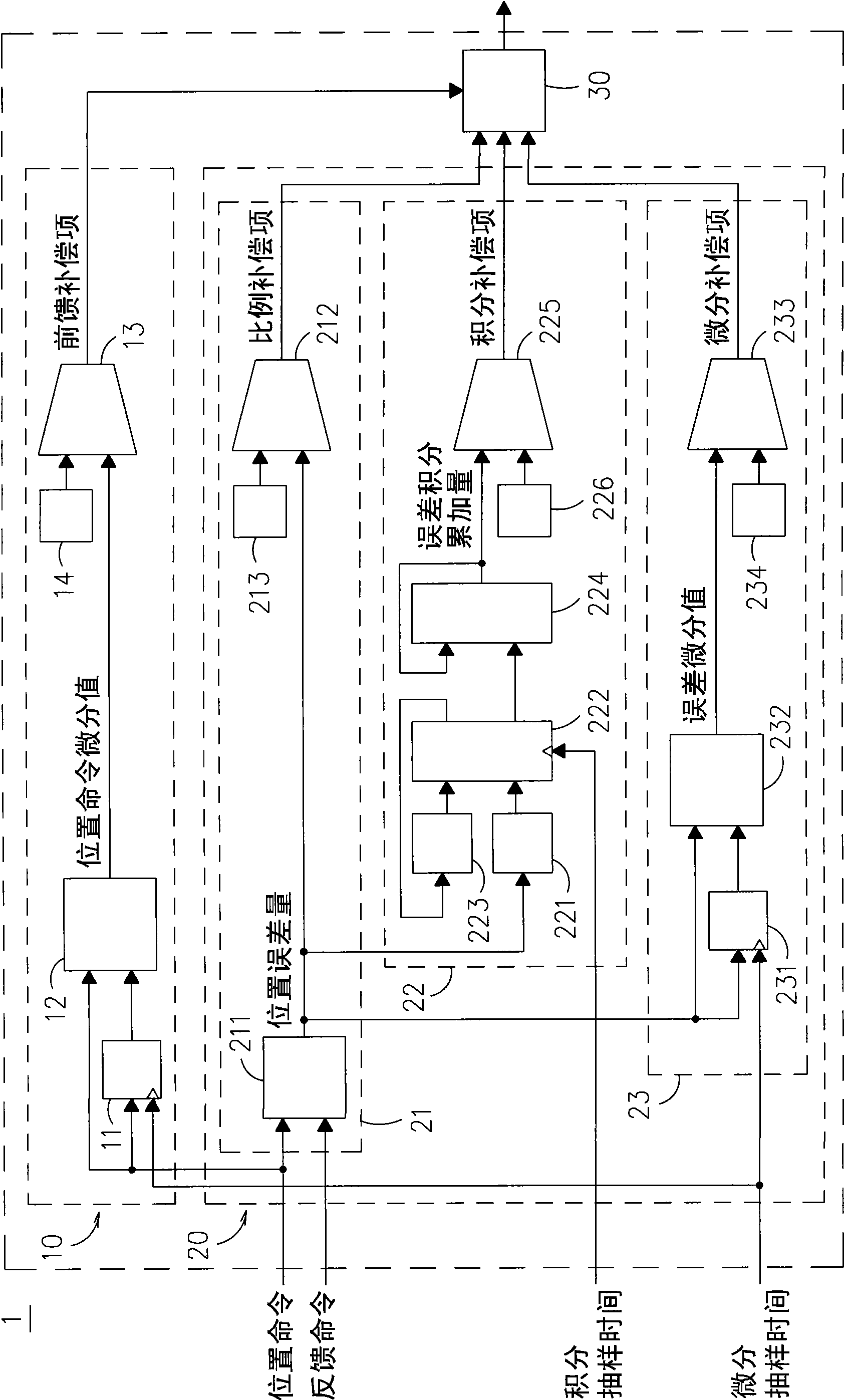
[0038] see figure 1 As shown, the structure diagram of the motion control service loop device provided by the present invention, the motion control service loop device mainly includes a feedforward control module 10, a proportional-integral-derivative (PID, Proportional-Integral-Derivative) control loop 20 and a compensation item adder 30 .

[0039] The feedforward control module 10 performs a differential operation on a position command through a temporary register 11 and a subtractor 12, and generates a position command differential, and then passes the position command differential through a multiplier 13 and a...


PUM


Abstract

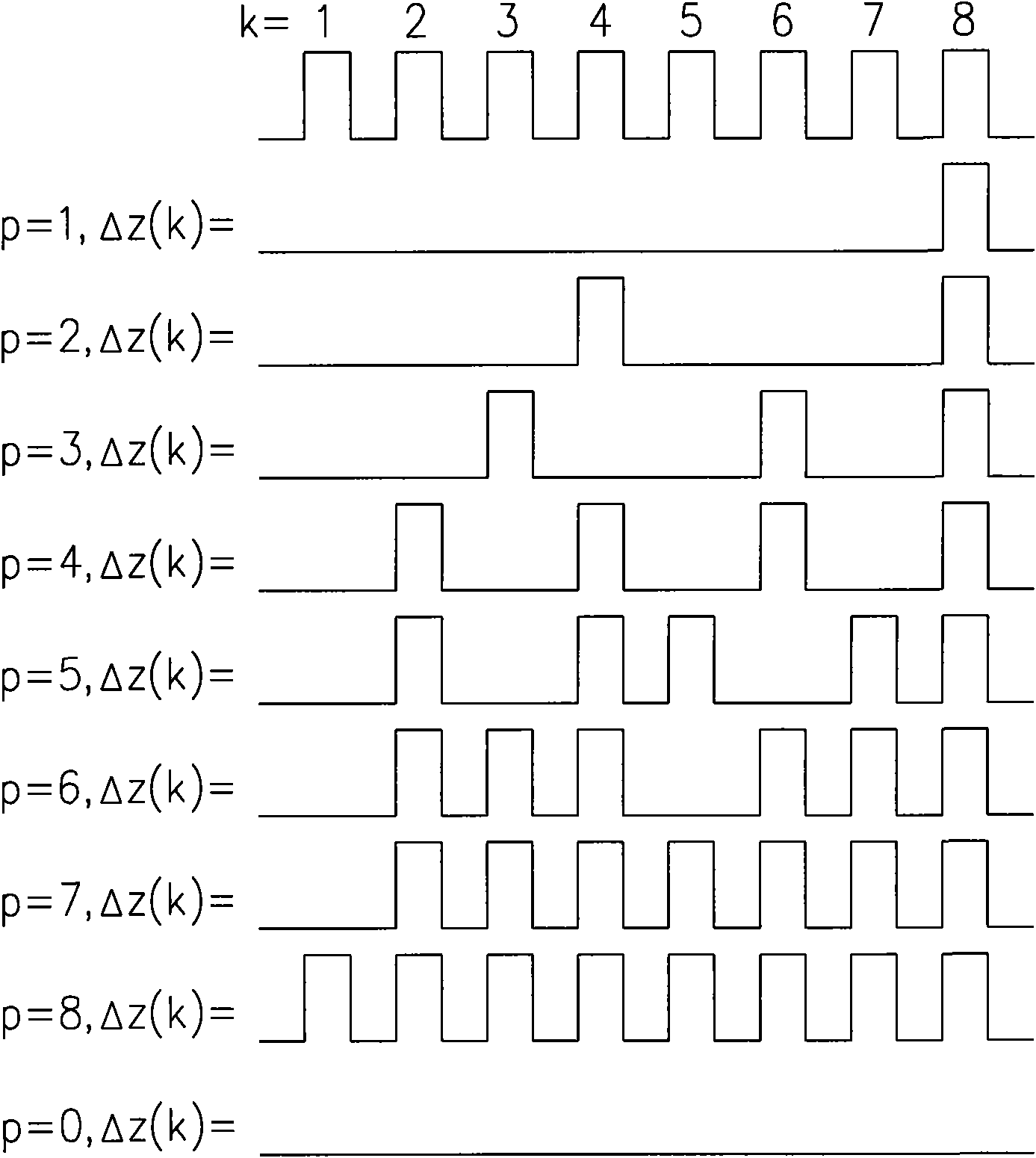
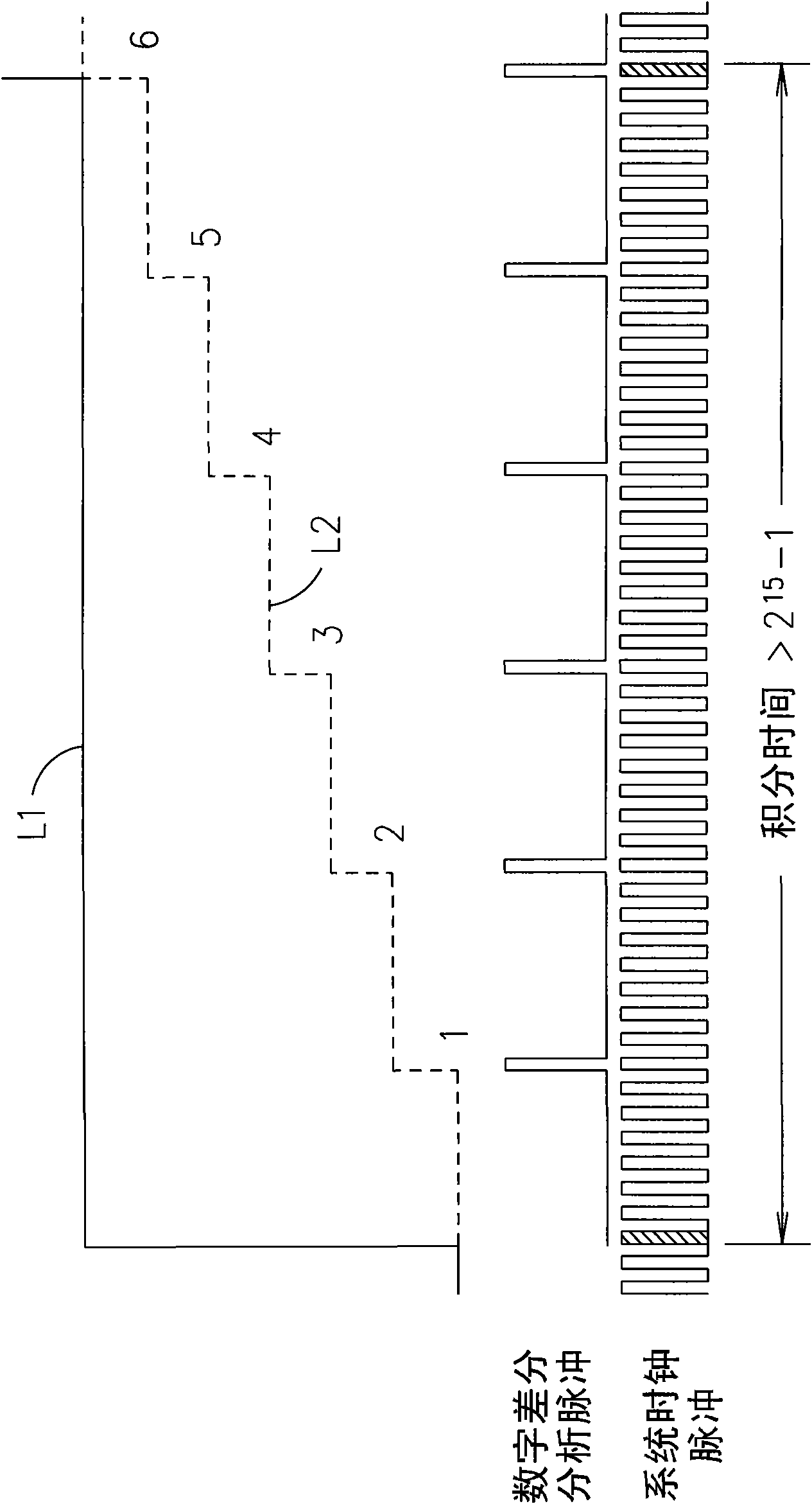
The invention relates to a movement control servo loop device, which comprises a feedforward control module, a proportional-integral-derivative control loop and a compensation term summator, wherein the feedforward control module can generate a feedforward compensation term; the proportional-integral-derivative control loop comprises a proportional control module, an integral control module and a derivative control module; the proportional control module can generate a proportional compensation term; and the derivative control module can generate a derivative compensation term. The integral control module adopts the digital difference to analyze calculation rules; in the time of each integral sampling, the magnitude of error is accumulated with the magnitude of position error at each moment of analyzing pulse generation by the digital difference, the integral action is carried out in sequence and an error integral cumulant is output, and then the error integral cumulant is processed to generate an integral compensation term; and then the compensation term summator receives the feedforward compensation term, the proportional compensation term, the integral compensation term and the derivative compensation term and calculates the compensation dosage of the movement position error of a drive.

Description

technical field [0001] The present invention relates to a motion control servo loop device, especially an integral control module that adopts a digital differential analysis (DDA, Digital Differential Analyzer) algorithm in a proportional-integral-derivative (PID, Proportional-Integral-Derivative) control loop It is a motion control servo loop device that can effectively improve the response speed, reduce the steady-state error, improve the transient response and compensate the delay phenomenon of the controlled system. Background technique [0002] Motion control technology is a common basic technology of various mechanical controllers. Its purpose is to regulate the speed, position and torque of motors used in various machines to drive tools or chucks in three-dimensional space, in the expected Automatic work such as cutting, processing, assembly, pick-and-place, etc. is carried out at the expected speed and along the expected trajectory. There are two types of known moti...

Claims


Application Information

Patent Timeline
Patent Type & Authority Applications(China)
IPC IPC(8): G05B11/42
Inventor 陈英敏陈文泉黄静宜吴承学林家庆沈万凯
Owner IND TECH RES INST
Learn More