
Card reader having function of electronic card and card insertion detection method thereof

An electronic card and card reader technology, which is applied in computer parts, record carriers and instruments used in machines, etc., to achieve the effect of prolonging standby and use time and reducing power consumption.

Inactive Publication Date: 2010-07-14
钟雅婷 +4
View PDF0 Cites 12 Cited by
  • Summary
  • Abstract
  • Description
  • Claims
  • Application Information

AI Technical Summary

Problems solved by technology

[0007] The main purpose of the present invention is to overcome the defects of the above-mentioned prior art, and provide a card reader with electronic card function and its card insertion detection method. The electronic card is housed inside the main body, and the main body is inserted into the USB type plug of the electronic product. slot or card connector, and switch to electronic card or card reader mode and power supply path switching through the switching mechanism, so that the main body has the functions and characteristics of electronic cards and card readers, and improves the related problems and problems arising from inconvenient use. missing

Method used


Image

  • Card reader having function of electronic card and card insertion detection method thereof
  • Card reader having function of electronic card and card insertion detection method thereof
  • Card reader having function of electronic card and card insertion detection method thereof

Examples


Embodiment Construction

[0030] In order to achieve the above-mentioned purpose and effect, the technical means and the structure adopted by the present invention are now illustrated in detail with respect to the preferred embodiments of the present invention. Its features and functions are as follows for complete understanding.

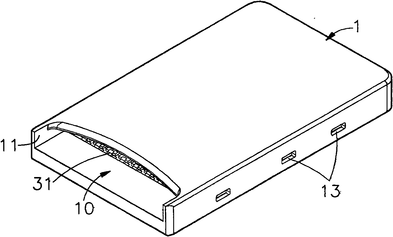
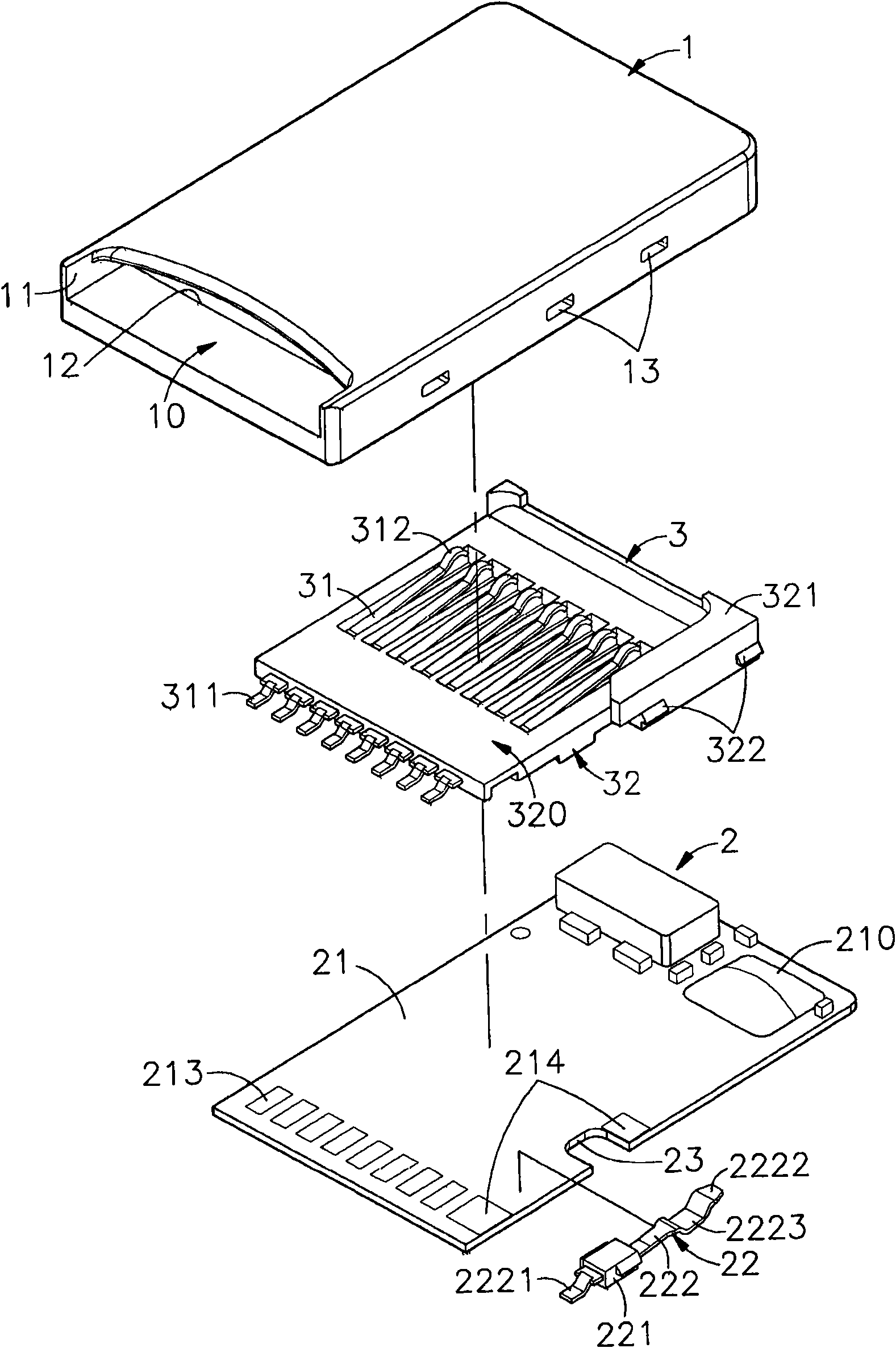
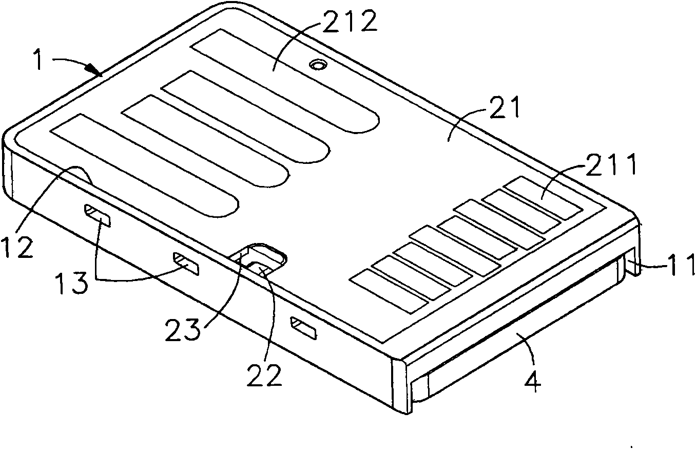
[0031] see Figure 1 to Figure 4 As shown, they are respectively the three-dimensional appearance diagram, the three-dimensional exploded view, the three-dimensional appearance diagram of another viewing angle and the use state diagram when inserting the card of the preferred embodiment of the present invention. It can be clearly seen from the figure that the present invention includes a main body 1 , circuit module 2 and terminal block 3, so the main components and their characteristics of this case are described in detail below, wherein:

[0032] The main body 1 is a hollow housing body, and the hollow part is formed with a housing space 10 for accommodating the circuit modu...


PUM


Abstract

The invention provides a card reader having the function of an electronic card and a card insertion detection method thereof. A circuit module and a terminal block are accommodated in a main body accommodating space, and one side of a main body is provided with a plug-in port through which a preset electronic card is inserted into the accommodating space; the front and back sides of a bottom surface of a circuit board of the circuit module are provided with a plurality of electronic card metal contacts which can be exposed from a bottom hollow groove of the main body and a USB type butt joint terminal; and after a joint end on one side of a conductive terminal arranged on the terminal block is electrically connected with a conductive terminal contact on the top surface of the circuit board, and a butt joint end on the other side of the conductive terminal extends into the accommodating space and is electrically contacted with the preset electronic card, the main body is inserted into a USB type slot of an external electronic product or an adaptive preset card connector and is switched to an electronic card or a card reader mode through a switching mechanism. Simultaneously, switching of a chip power supply channel can be controlled, and then a signal transmission action is performed on the preset electronic card, so the functions and properties of the electronic card and the card reader can be integrated into the same main body to solve the problem of inconvenient use.

Description

technical field [0001] The invention relates to a card reading device, in particular to a card reading machine with electronic card function and a card insertion detection method thereof. Background technique [0002] Today's technology is changing with each passing day, the rise of the digital age, and the widespread use and popularity of handheld personal digital electronic products have created a huge flash memory market. In order to meet market demand, major flash memory suppliers and electronic product manufacturers are jointly launching a A series of electronic cards (flash memory cards), thus meeting a large number of needs of consumers. [0003] In addition, due to the breakthrough development of flash memory card storage capacity and transmission speed, many memory cards with smaller volume and larger memory capacity have been launched one after another. From the beginning, digital security card (SD card) and multimedia card (MMC card) , memory stick (MS card), etc...

Claims


Application Information

Patent Timeline
IPC IPC(8): G06K7/00G06K19/07
Inventor 钟雅婷曾吴秋香钟国宛钟育闳黄冠霖
Owner 钟雅婷
Learn More