Device for drawing intermediate roll of eighteen-roll cold-rolling mill

A technology of intermediate rolls and cold rolling mills, which is applied in the direction of metal rolling stands, metal rolling mill stands, and metal rolling. Low cost, convenient roll replacement, and space-saving effects

Inactive Publication Date: 2010-07-21
WUXI WUYE METAL ROLLING
View PDF0 Cites 4 Cited by
  • Summary
  • Abstract
  • Description
  • Claims
  • Application Information

AI Technical Summary

Problems solved by technology

The twitching device of the existing rolling mill generally adopts the way of installing the twitching bracket on the rolling mill archway, and driving the twitched roll bearing seat through multiple hydraulic cylinders, motor reducers, hydraulic motor reducers or manual worm gear reducers. Such a twitching method , the twitching device must be installed on the transmission side of the rolling mill, and often leads to adverse consequences such as a large structure of the twitching device, inconvenience in changing rolls, and high equipment maintenance costs

Method used


Image

  • Device for drawing intermediate roll of eighteen-roll cold-rolling mill
  • Device for drawing intermediate roll of eighteen-roll cold-rolling mill
  • Device for drawing intermediate roll of eighteen-roll cold-rolling mill

Examples


Embodiment Construction

[0015] The present invention will be further described below in conjunction with specific drawings and embodiments.

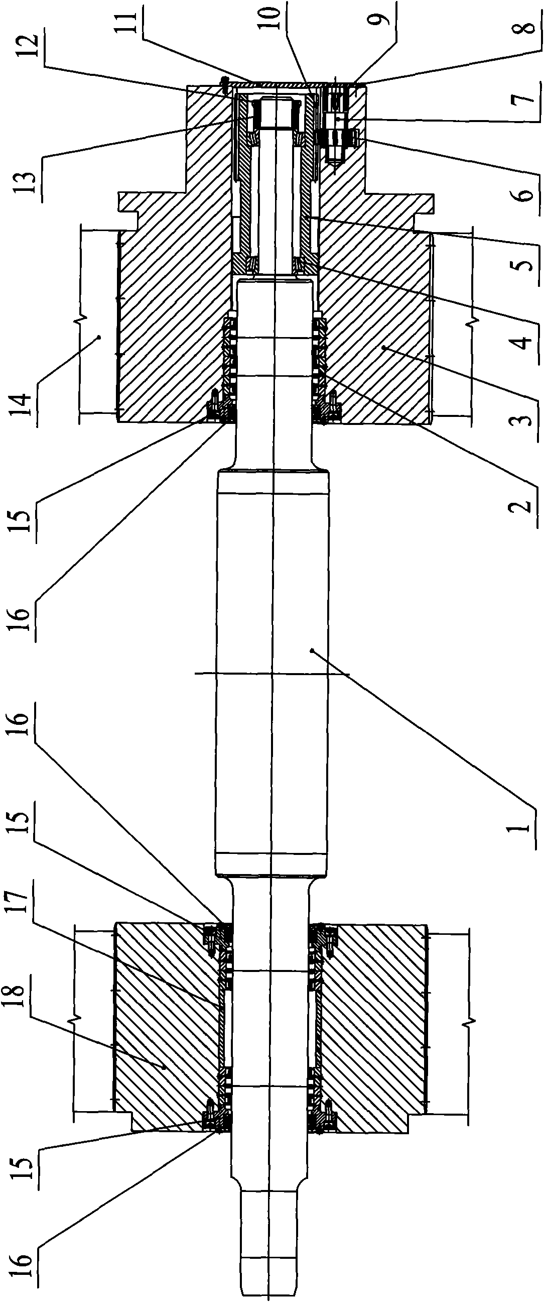
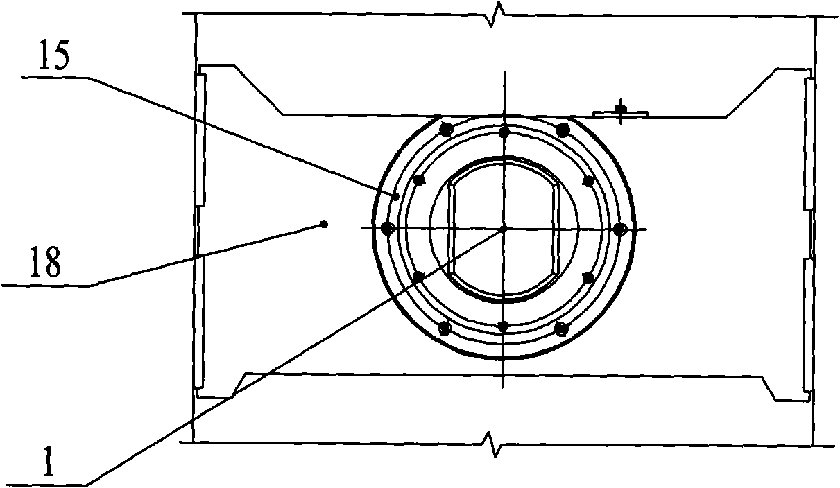
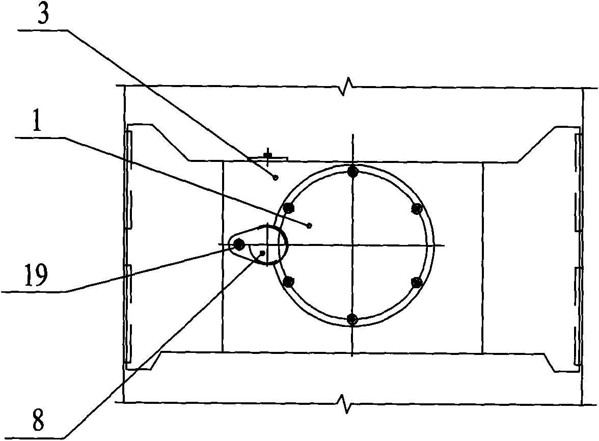
[0016] As shown in the figure, the present invention mainly consists of an intermediate roller 1, an intermediate roller bearing seat 2 on the operation side, an FC bearing without an inner ring 3, a tapered roller bearing 4, a threaded gear sleeve 5, a twitching gear 6, a twitching gear pin 7, a twitching gear Gear locking plate 8, end cover 11, nut 12, gland 13, rolling mill archway slideway 14, bearing end cover 15, sealing gasket 16, locking screw 19, spacer sleeve 17, drive side intermediate roll bearing housing 18 and other components are assembled. become.

[0017] Such as Figure 1 ~ Figure 3 As shown, the middle roller bearing housing 2 on the operation side and the middle roller bearing housing 18 on the driving side are respectively installed in the slideway 14 of the rolling mill archway in a conventional manner. Sliding up and down; the operating...


PUM


Abstract

The invention relates to a device for drawing an intermediate roll of an eighteen-roll cold-rolling mill. The invention adopts a technical scheme that: the operating end and transmission end of the intermediate roll are arranged on an operating-side intermediate roll bearing block and a transmission-side intermediate roll bearing block through an inner ring-free FC bearing respectively; the operating end of the intermediate roll is sleeved and fixed with a helical geared sleeve; the outer sidewall of the inner end of the helical geared sleeve is provided with an outside thread; an internal thread is arranged in the operating-side intermediate roll bearing block and is meshed with the outside thread; the outer sidewall of the outer end of the helical geared sleeve is provided with a driven gear of which one side is provided with a drawing gear meshed with the driven gear; the drawing gear is arranged on the operating-side intermediate roll bearing block through a drawing gear pin shaft, is fixedly connected with the drawing gear pin shaft and can synchronously rotate with the drawing gear pin shaft; and the outer end of the drawing gear pin shaft is provided with a crank hole. The device has the characteristics of greatly simplifying the structure of the drawing device, reducing occupied space of the drawing device and facilitating the replacement of the intermediate roll, along with compact and rational structure, convenient roll replacement and low maintenance cost.

Description

technical field [0001] The invention belongs to the technical field of mechanical equipment, and in particular relates to a manual twitching device for an intermediate roll of a high-precision strip eighteen-high cold rolling mill. Background technique [0002] In order to enhance roll bending efficiency, expand roll shape adjustment range, and stabilize plate shape quality, four-roll and above rolling mills are usually equipped with work roll or intermediate roll twitching devices. The twitching device of the existing rolling mill generally adopts the way of installing the twitching bracket on the rolling mill archway, and driving the twitched roll bearing seat through multiple hydraulic cylinders, motor reducers, hydraulic motor reducers or manual worm gear reducers. Such a twitching method , The twitching device must be installed on the transmission side of the rolling mill, and often leads to adverse consequences such as a large structure of the twitching device, inconve...

Claims


Application Information

Patent Timeline
Patent Type & Authority Applications(China)
IPC IPC(8): B21B31/18
Inventor 周小萍
Owner WUXI WUYE METAL ROLLING
Why Eureka
Try Eureka