
Vertical coaxial anti-explosion fire-retardant breather valve

A breathing valve, coaxial technology, applied in the direction of container, packaging, transportation and packaging, etc., can solve the problems of blocked passage, inability to operate correctly, medium condensation and blockage, etc., to reduce the number of repairs and maintenance, easy installation and disassembly , the effect of prolonging the service life

Inactive Publication Date: 2010-07-21
抚顺华海石油机械制造有限公司 +1
View PDF0 Cites 9 Cited by
  • Summary
  • Abstract
  • Description
  • Claims
  • Application Information

AI Technical Summary

Problems solved by technology

Because the explosion-proof flame arrester is very close to the storage tank, condensation and blockage often occur due to the self-accumulation of the medium, the channel is not smooth, and the breathing valve does not work properly, so it is prone to safety hazards such as storage tank collapse
In addition, the above-mentioned explosion-proof and fire-resistant breathing valves are generally arranged horizontally or sideways, which will cause the overall center of gravity of the equipment to shift instead of the center of the fixed flange of the base, resulting in uneven pressure on the top of the storage tank. The loading and unloading or maintenance of the top of the tank is extremely inconvenient, it is difficult to clean sideways, and the operation of sideways maintenance and replacement of parts is difficult, which brings great hidden dangers to the operator's operation safety
[0003] Also provided in the prior art is an explosion-proof fire-stop breathing valve for oil storage tanks that integrates an explosion-proof flame arrester and a breather valve into one, which first fires and then breathes. The explosion-proof flame arrester of the valve and the pressure valve disc of the breather, Although the vacuum valve disc is coaxially arranged, the gas flow passages of the valve's "exhale" and "inhale" are set on the side of the valve body, so that the force on the pressure valve disc and the vacuum valve disc is in an uneven state for a long time. The guide rod is also in an uneven stress state, which will directly cause the guide rod to be biased or the side wear will cause the pressure valve and vacuum valve to fail earlier
In addition, the vacuum valve of this technology is on the bottom and the pressure valve is on the top, and the suction port of the vacuum valve is smaller than the exhalation port of the pressure valve, and the flow rate of the breathing port of the protective cover is very small, which is also one of the reasons for the collapse of the tank. This is a structural hidden danger that has been proven in the production practice of the same industry
In particular, in this technology, there are only screws on the vacuum disk seat and pressure disk seat without a pressure plate ring. Due to the long-term changes in winter and spring and the temperature change of the medium in the tank, the disk seat often deforms irregularly, resulting in pressure valve disk or The vacuum valve disc cannot achieve the sealing effect with the disc seat, which will inevitably cause the pressure valve disc or the vacuum valve disc to be in the normal open state at the same time or only one, and cannot perform the functions of "exhalation" and "suction", resulting in waste of media and equipment. scrapping
If the valve seat fails to be replaced, the site will not be able to operate correctly, and the level of the disc seat cannot be correctly determined, so the normal operation of the breathing valve cannot be guaranteed

Method used


Image

  • Vertical coaxial anti-explosion fire-retardant breather valve
  • Vertical coaxial anti-explosion fire-retardant breather valve
  • Vertical coaxial anti-explosion fire-retardant breather valve

Examples


Embodiment Construction

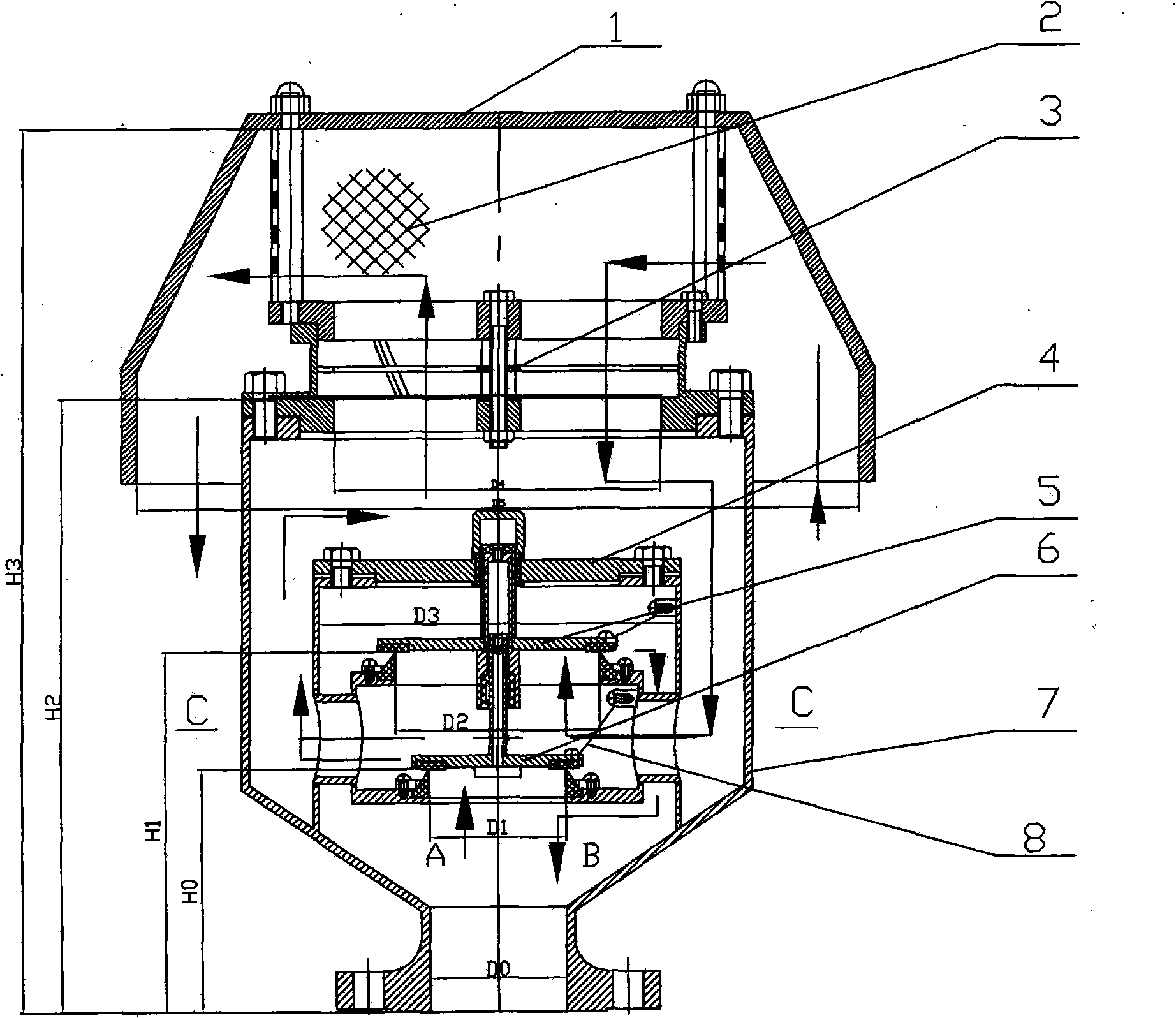
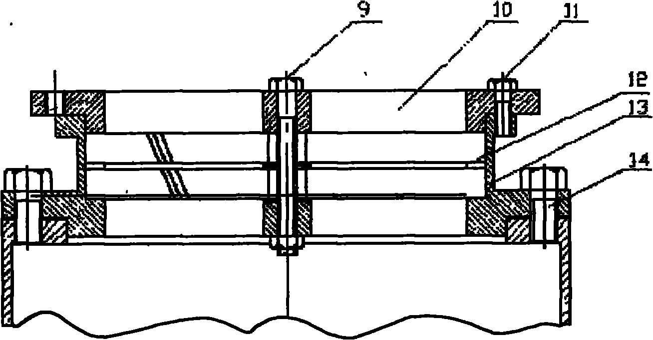
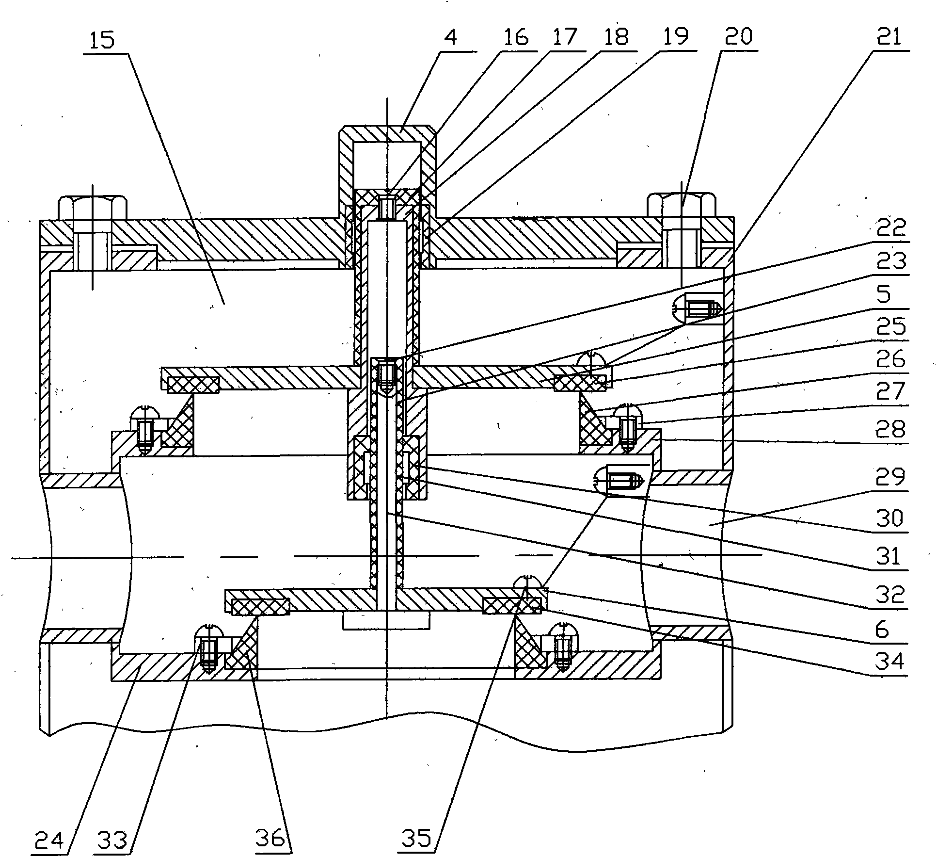
[0011] figure 1 The vertical coaxial explosion-proof flame arresting breathing valve given in is composed of an explosion-proof flame arrester 3 and a breathing valve. The lower part of the outer casing 7 of the present invention is a reducing flange connected with the storage tank. The breather valve is installed in the outer shell 7 of the present invention, and the explosion-proof flame arrester 3 is installed on the top of the outer shell 7 . figure 1 The arrow direction A in the figure is the gas flow path of the "exhale" action, and B is the gas flow path of the "inhale" action. Such as figure 2 As shown, the explosion-proof flame arrester 3 is composed of a fire-blocking layer seat 13 , a fire-blocking layer 12 and a fire-blocking laminate ring 10 connected together by a long rod bolt 9 . 11,14 are connecting bolts. The flame-retardant layer 12 of the explosion-proof flame arrester 3 adopts a stainless steel explosion-proof and fire-proof double-layer oblique wave ...


PUM


Abstract

The invention belongs to fire-retardant ventilation equipment of a petroleum storage tank, which consists of an anti-explosion flame arrester and a breather valve. The flame arrester is positioned at the top and plays a role in preventing explosion first and then preventing fire. The top of a breather valve cavity consisting of a vacuum valve and a pressure valve is provided with a pressure cavity sealing guide sleeve cover. The vertical movement of a vacuum valve disk is restrained by a guide sleeve of the pressure cavity sealing guide sleeve cover, and the vertical movement of a pressure valve disk is restrained by a guide rail of the vacuum valve disk. The fire-retardant ventilation equipment has reasonable design. Particularly, the pressure cavity sealing guide sleeve cover at the breather valve further plays a role in blocking the breather valve and the anti-explosion flame arrester, effectively adds the functions of flame arrest and explosion prevention, and enhances the safety and reliability of the whole equipment. The vertical coaxial symmetrical mounting structure stabilizes the center of the equipment; and the pressure valve disk and the vacuum valve disk are stressed uniformly so as to prolong the service life of the equipment, reduce the maintenance frequency and the production cost, facilitate assembly and disassembly, facilitate the operation and maintenance of a tank top and improve the production efficiency.

Description

1. Technical field [0001] The invention belongs to the fire-blocking and ventilating equipment of petroleum storage tanks—a vertical coaxial explosion-proof fire-blocking breathing valve, which is installed on the petroleum storage tanks, can ensure fire-blocking ventilation, ensure that the internal pressure of the petroleum storage tanks is in a safe state, and can Reduce the evaporation loss of oil products. 2. Background technology [0002] According to the relevant national and industry standards, fixed storage tanks for Class A and B liquids should be equipped with flame arresters and breathing valves. Therefore, it can be seen that flame arresters and breathing valves are indispensable safety measures and equipment for storage tanks such as oil products or chemical products. The explosion-proof flame arrester is to prevent the flame outside the tank from entering to ensure the safety of the storage tank. The breathing valve can adjust and maintain the automatic bala...

Claims


Application Information

Patent Timeline
Patent Type & Authority Applications(China)
IPC IPC(8): B65D90/22B65D90/32
Inventor 王楠王庆铎王维
Owner 抚顺华海石油机械制造有限公司
Learn More