
Full-automatic pulp-molding roller molding machine

A pulp molding and forming machine technology, applied in textiles and papermaking, etc., can solve the problems of high labor intensity of workers, increase production costs, low cost performance, etc., and achieve the effects of protecting the environment, saving resources and overcoming waste.

Active Publication Date: 2010-07-21
XIANGTAN SHUANGHUAN MACHINERY DEV
View PDF5 Cites 10 Cited by
  • Summary
  • Abstract
  • Description
  • Claims
  • Application Information

AI Technical Summary

Problems solved by technology

[0002] At present, in the pulp molding industry, egg trays, egg boxes, fruit trays, bottle trays and other paper trays are made of recycled waste paper. The molding equipment used is a reciprocating molding machine, which belongs to small equipment and relies on manual operation. Manipulating one pallet at a time, the output is low, and the labor intensity of workers is high, which can only meet the production of small batches of products with small area and simple shape; the gap rotary molding machine has only one transfer drum, which can only be pressed once for one revolution. Most of the time is spent in idling motion, resulting in a lot of equipment waste and energy waste, which relatively increases the production cost of the product, and the structure is complex and the cost performance is low.

Method used


Image

  • Full-automatic pulp-molding roller molding machine
  • Full-automatic pulp-molding roller molding machine
  • Full-automatic pulp-molding roller molding machine

Examples


Embodiment Construction

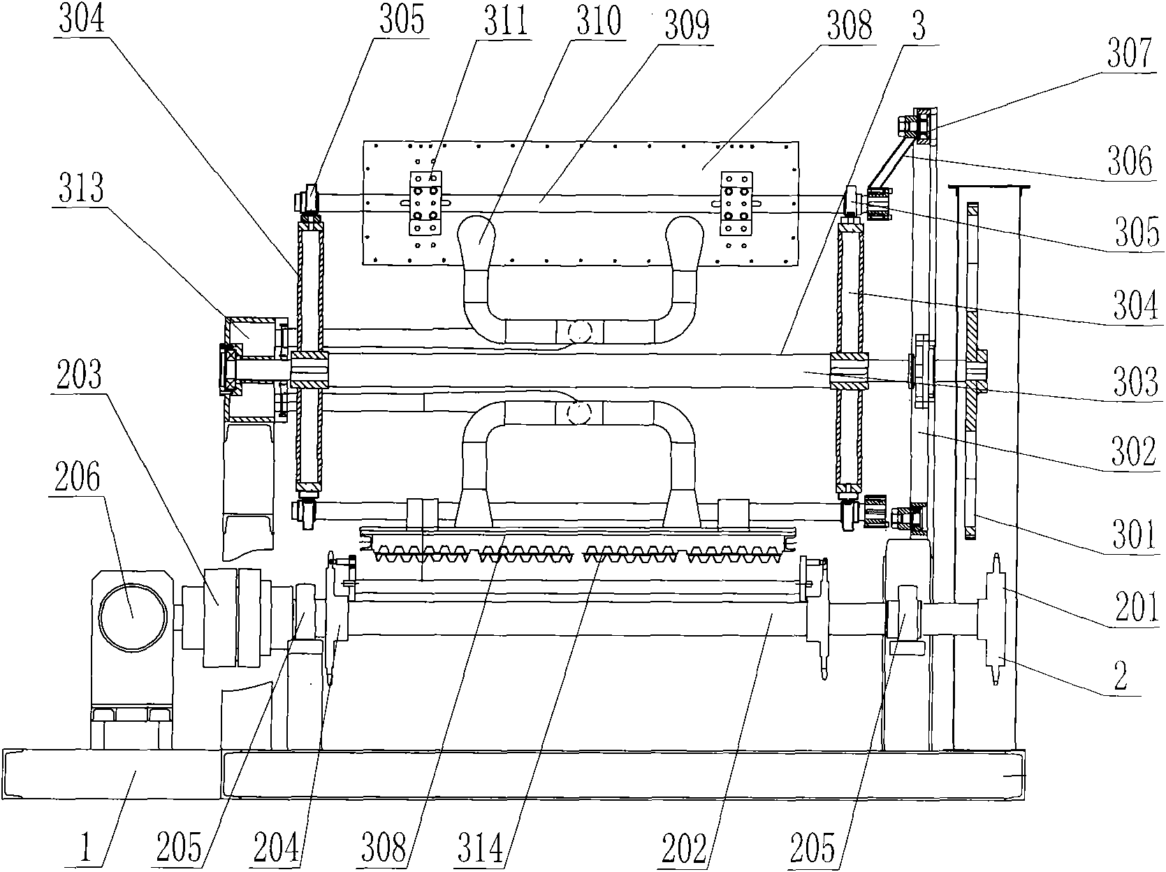
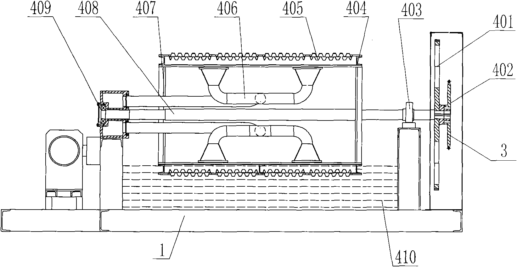
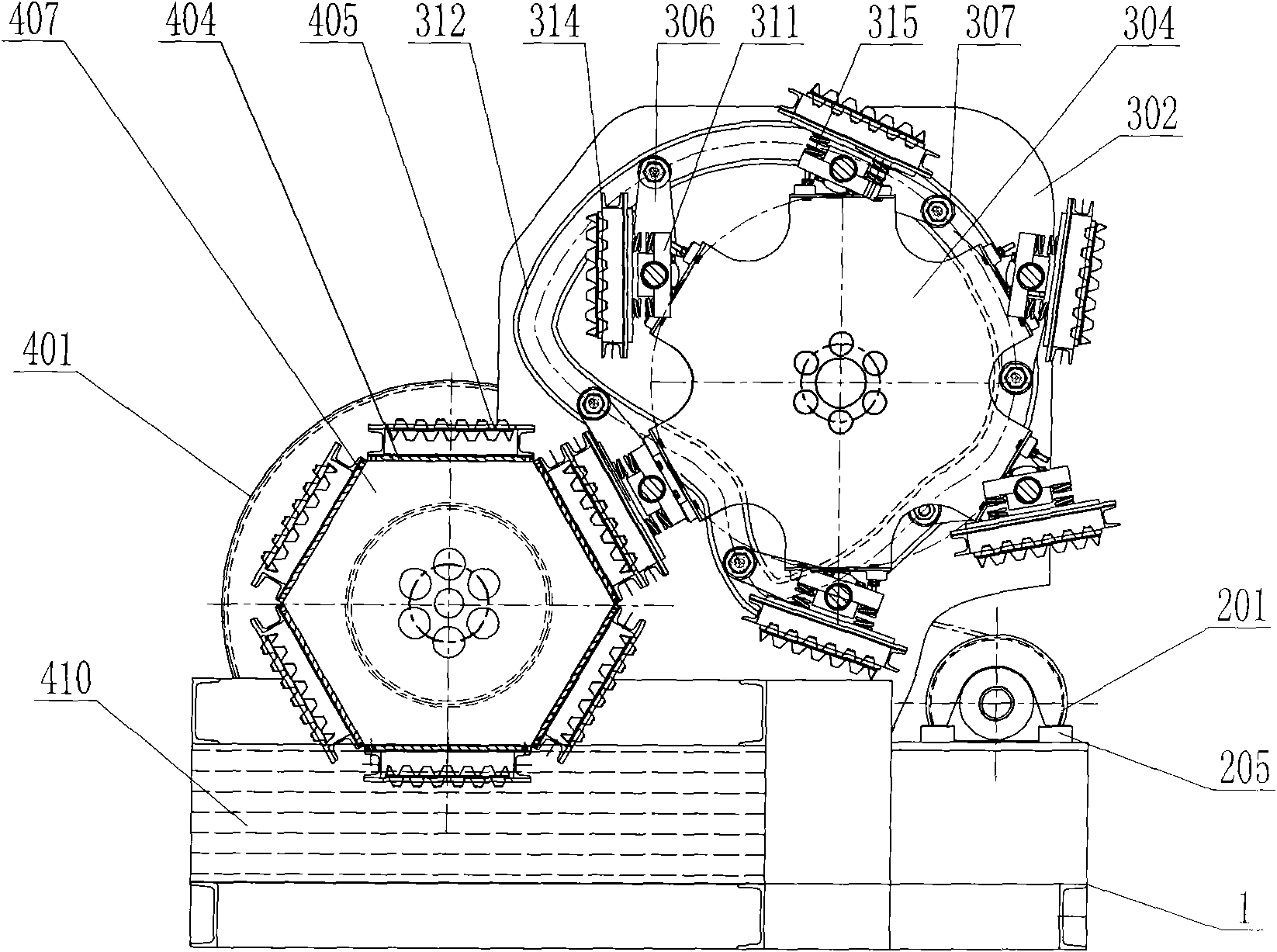
[0025] by attached figure 1 , figure 2 , image 3 , Figure 4 As shown, a fully automatic pulp molding machine is composed of a frame 1, a drying transmission device 2, a transfer drum 3, and a slurry suction drum 4; the drying transmission device 2 includes a small sprocket 201 solid Installed on one end of the transmission shaft 202, the transmission shaft 202 is movably connected with the two bearing seats I205, the other end of the transmission shaft 202 is connected to the speed reducer 203, the speed reducer 203 is connected to the speed regulating motor 206, and two transmission pulleys 204 are fixedly installed on the transmission shaft 202; Drum 3 includes a gear 301 fixed on one end of the upper main shaft 303, one side of the upper main shaft 303 is movably installed on the side frame 302, and the other side is movably installed in the bearing of the pulp distribution box 313, and the two sides of the upper main shaft 303 are fixedly supported Frame 304, the two...


PUM


Abstract

The invention discloses a full-automatic pulp-molding roller molding machine. A gear of a transfer rotary drum is fixed on one end of an upper main shaft. One side of the upper main shaft is movably arranged on a side frame, and the other side of the upper main shaft is movably arranged in a bearing of a pulp distribution box. Supporting brackets are fixedly arranged on two sides of the upper main shaft. Six rotating shafts are connected to the two supporting brackets, and each rotating shaft elastically fixes an upper mold mounting plate through a press plate and a spring. An upper pipeline is arranged on the bottom surface of the upper mold mounting plate, on which an upper mold is fixed. A crank arm is fixedly arranged at one end of each rotating shaft, and is connected with a roller. The roller and a track cam are in flexible connection. A driving gear and a chain wheel are fixedly arranged at one end of a lower main shaft of a pulp-absorption rotary drum, and the lower main shaft is supported by a left bearing block and a right bearing block. Six rotary drums are fixedly arranged on the lower main shaft, and six lower mold mounting plates are arranged on the six rotary drums. A lower mold is fixedly arranged on each lower mold mounting plate, and a lower pipeline is arranged on the bottom surface of each lower mold mounting plate. Due to the scheme of drying and transmitting products by a drying transmission device, the defect that the traditional pulp-molding molding machines have low working efficiency is overcome. The full-automatic pulp-molding roller molding machine is applied to manufacturing various paper-molded trays.

Description

technical field [0001] The invention relates to a full-automatic pulp molding pair-to-roll forming machine. Background technique [0002] At present, in the pulp molding industry, egg trays, egg boxes, fruit trays, bottle trays and other paper trays are made of recycled waste paper. The molding equipment used is a reciprocating molding machine, which belongs to small equipment and relies on manual operation. Manipulating one pallet at a time, the output is low, and the labor intensity of workers is high, which can only meet the production of small batches of products with small area and simple shape; the gap rotary molding machine has only one transfer drum, which can only be pressed once for one revolution. Most of the time is idling, causing a lot of equipment waste and energy waste, relatively increasing the production cost of the product, and the structure is complicated and the cost performance is low. Contents of the invention [0003] In view of the above situation...

Claims


Application Information

Patent Timeline
Patent Type & Authority Applications(China)
IPC IPC(8): D21J3/00
Inventor 周斌辉巢邕
Owner XIANGTAN SHUANGHUAN MACHINERY DEV
Learn More