

Method and device for regulating emission surface of ultrasonic transducer probe to be parallel to reflecting plate
A reflector, ultrasonic technology, applied in the measurement of ultrasonic/sonic/infrasonic waves, measuring devices, instruments, etc., can solve the problems of insufficient reliability and accuracy, reducing experimental efficiency and effect, time-consuming and laborious, etc., achieving high accuracy, concise operation, Adjustable effects
- Summary
- Abstract
- Description
- Claims
- Application Information
AI Technical Summary
Problems solved by technology
Method used
Image

Examples
Embodiment
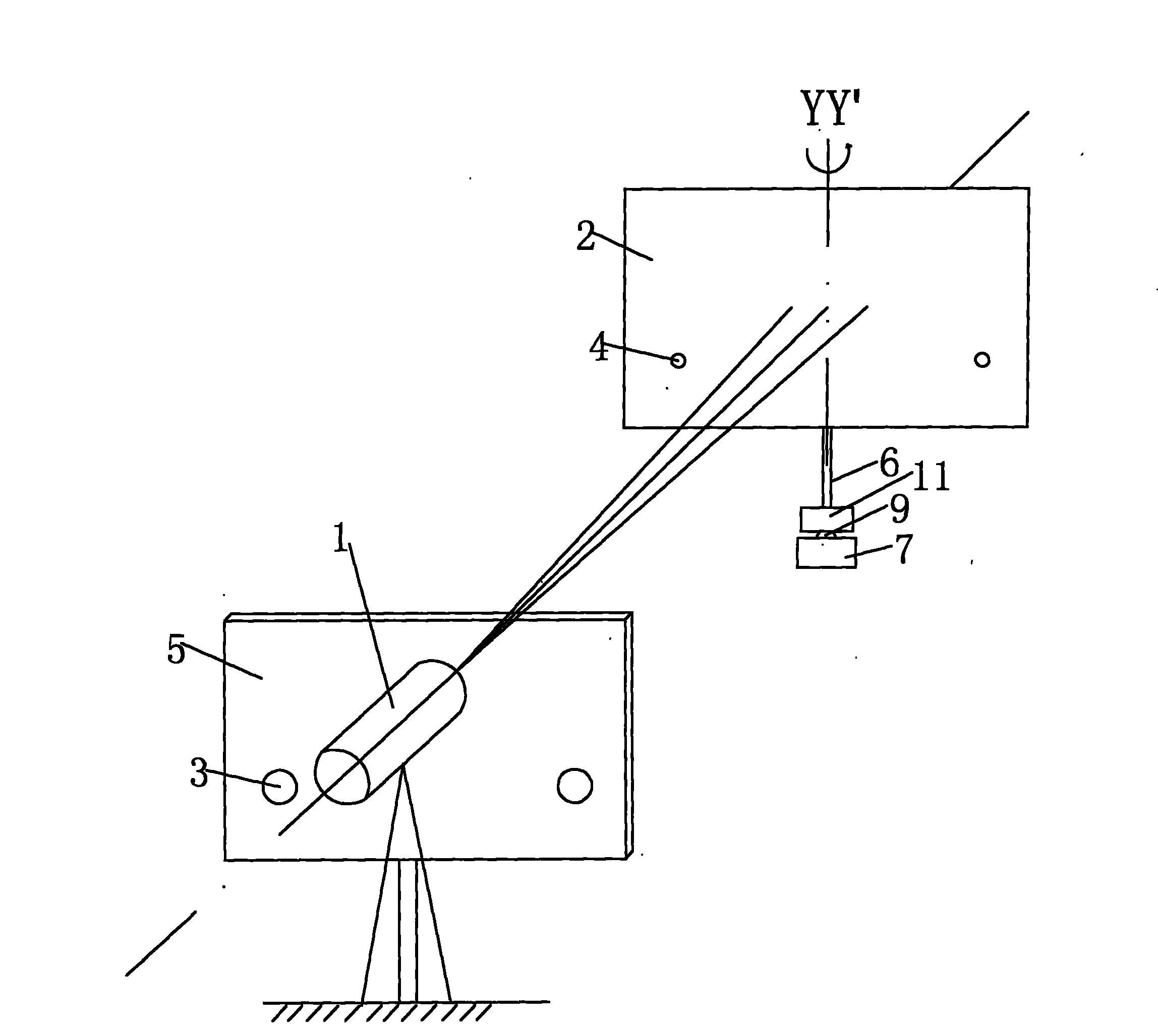
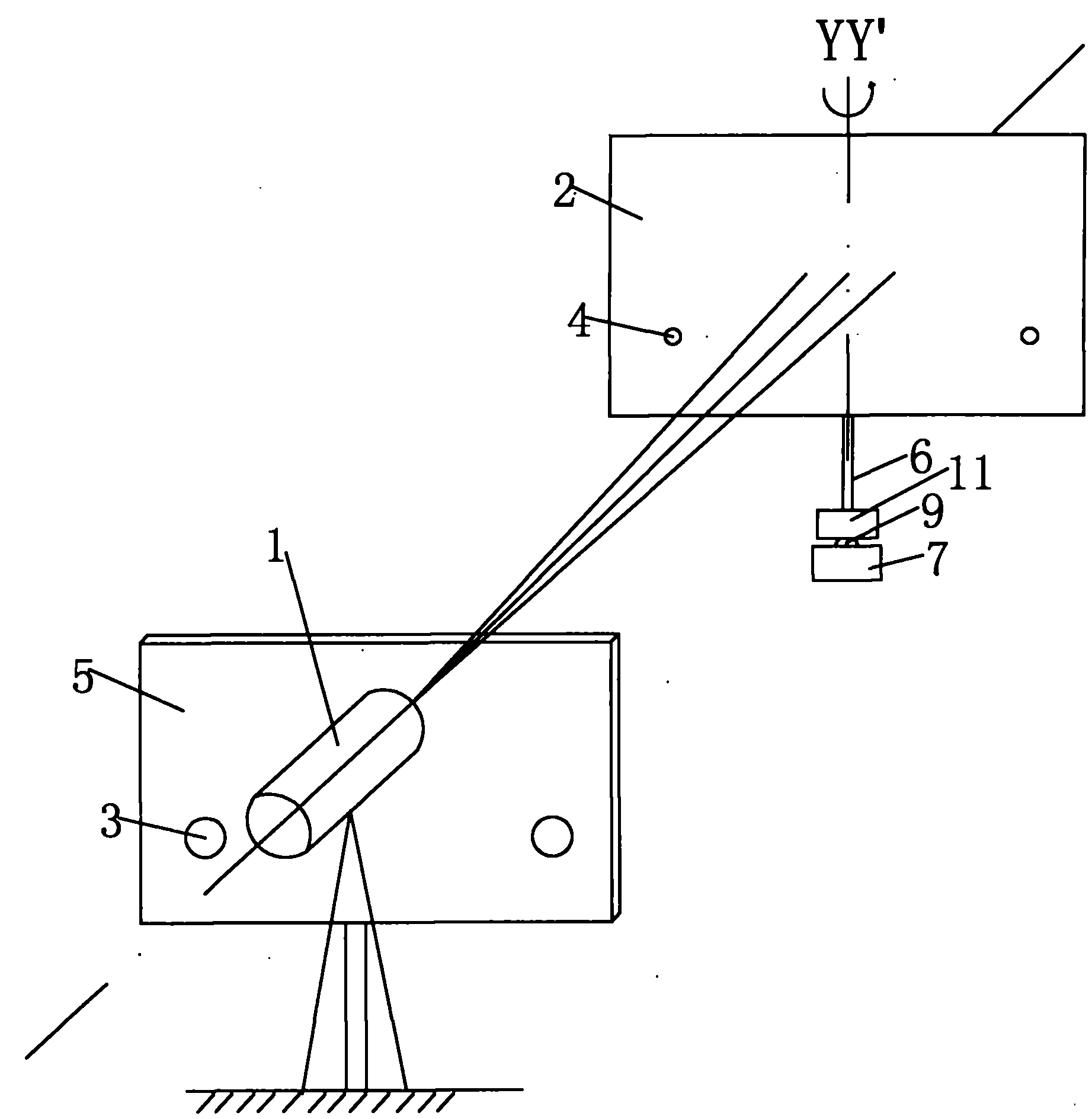
[0019] Embodiment: a method for adjusting the emitting surface of the ultrasonic transducer probe to be parallel to the reflector, comprising the steps of:
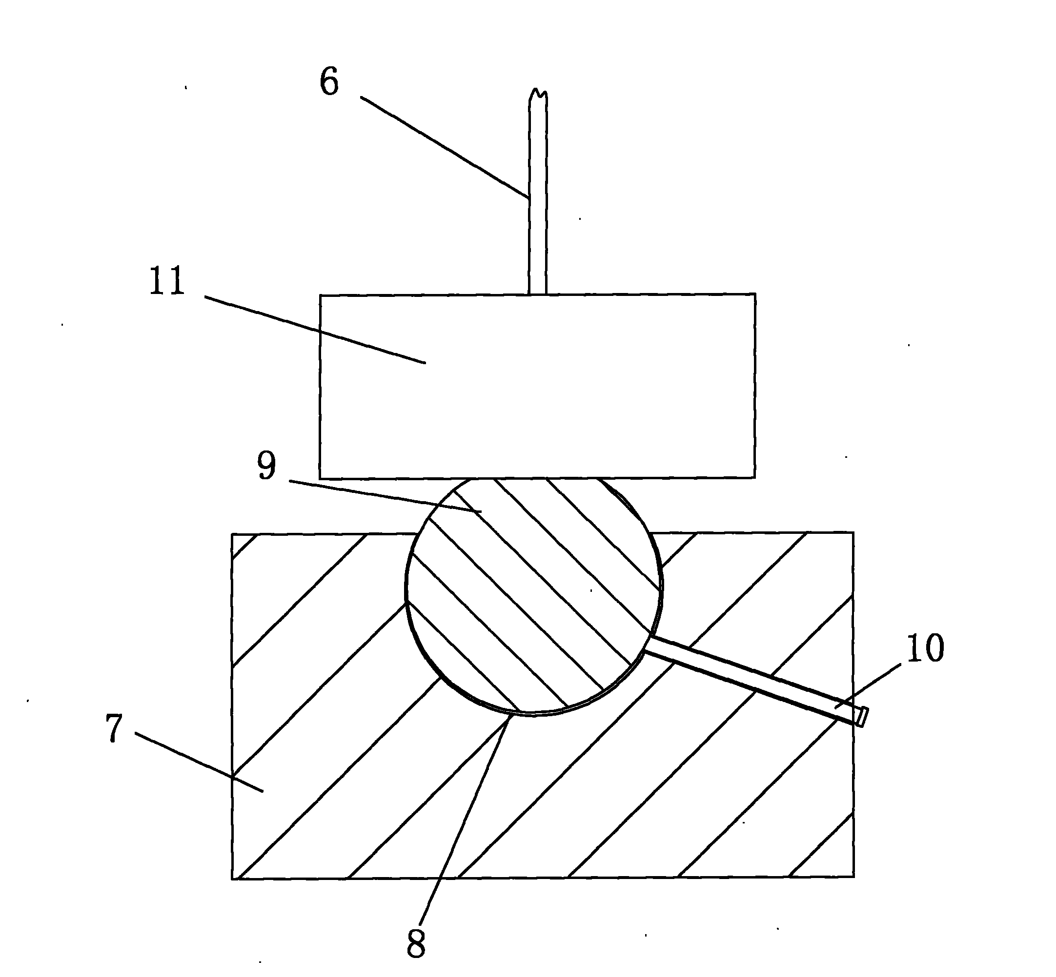
[0020] (1), install two laser transmitters on the side of the ultrasonic transducer probe, and adjust the position of the laser transmitter so that the emitted laser light is perpendicular to the emitting surface of the probe, and two laser receiving points are correspondingly installed on the reflector Sensor, first adjust when the ultrasonic transducer probe’s emitting surface is initially parallel to the reflector, the two laser beams emitted by the laser transmitter are just aligned with the two laser receiving point sensors in the reflector respectively; the initial parallel adjustment method is as follows : Start the ultrasonic transducer probe, connect the ultrasonic transducer probe to the oscilloscope, repeatedly adjust the position of the reflector, and use the oscilloscope to observe the ultrasonic echo return t...
PUM
 Abstract
Description
Claims
Application Information