
Bistable-state permanent magnet mechanism of parallel magnetic circuits

A permanent magnet mechanism and bistable technology, applied in the direction of protection switch operation/release mechanism, circuit, high-voltage air circuit breaker, etc., can solve the problems of large and short-term working current, increased investment in DC system, and reduced reliability, etc., to achieve The effect of reducing investment, reducing excitation magnetic potential and increasing holding force

Inactive Publication Date: 2012-01-18
SOUTHEAST UNIV
View PDF0 Cites 0 Cited by
  • Summary
  • Abstract
  • Description
  • Claims
  • Application Information

AI Technical Summary

Problems solved by technology

Because the closing and opening operation of the traditional permanent magnet mechanism requires a large magnetic force, if the number of coil turns of the permanent magnet mechanism is fixed, the DC power supply needs to provide a relatively large short-term operating current, resulting in increased investment in the DC system and reduced reliability

Method used


Image

  • Bistable-state permanent magnet mechanism of parallel magnetic circuits
  • Bistable-state permanent magnet mechanism of parallel magnetic circuits
  • Bistable-state permanent magnet mechanism of parallel magnetic circuits

Examples


Embodiment Construction

[0016] The accompanying drawings disclose the specific structures of the embodiments of the present invention without limitation, and the present invention will be further described below in conjunction with the accompanying drawings.

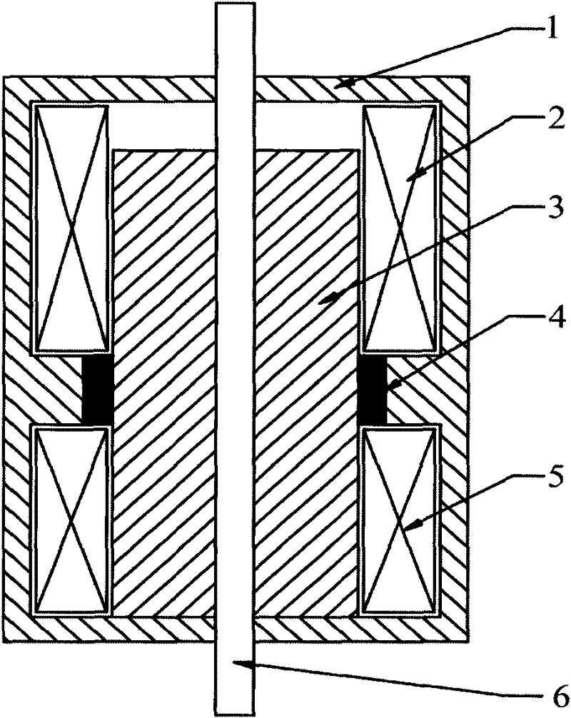
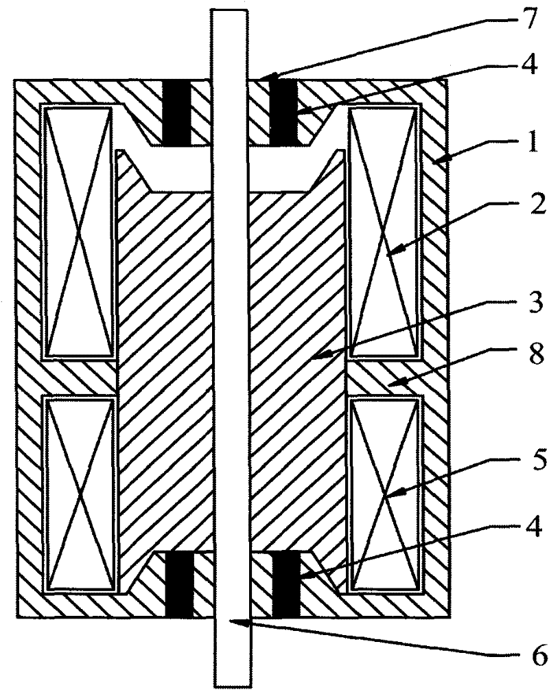
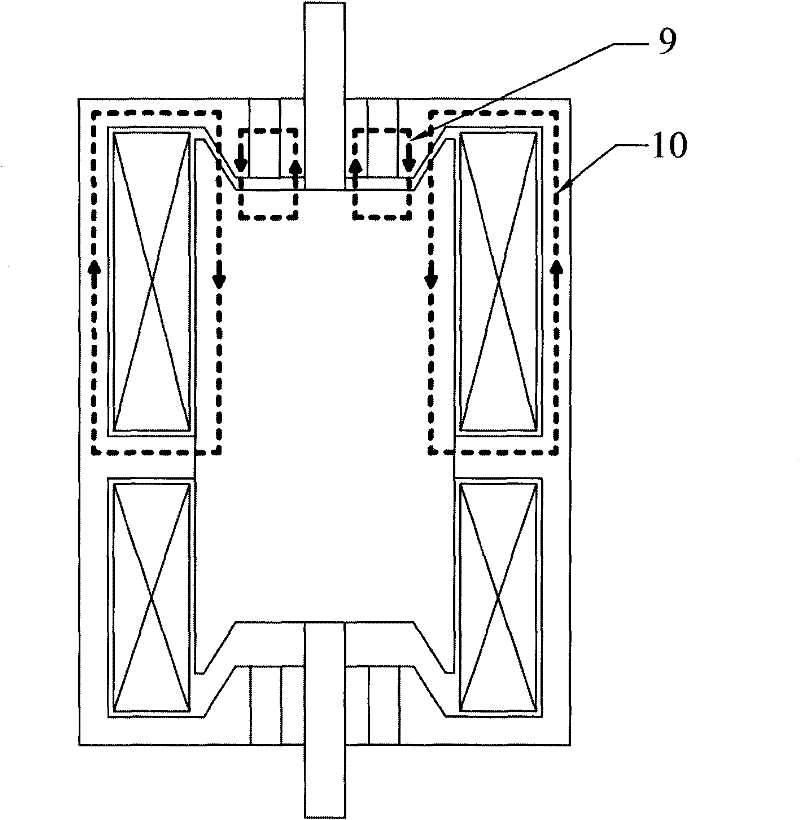
[0017] Depend on figure 2 It can be seen that a bistable permanent magnet mechanism with a parallel magnetic circuit includes a moving iron core, a static iron core, a coil and a permanent magnet. For the coil and the opening coil, an annular permanent magnet is arranged inside the end face of the static iron core, and a magnetic sleeve is arranged inside the annular permanent magnet. The moving iron core has a space for the moving iron core to move between the moving iron core and the end cover of the static iron core. The contact surface between the moving iron core and the end surface of the static iron core is set in the shape of an inclined platform, the end of the static iron core is in the shape of a convex platform, and the end of the...


PUM


Abstract

The invention relates to a bistable-state permanent magnet mechanism of parallel magnetic circuits, comprising a static iron core (1), a movable iron core (3), closing coils (2), opening coils (5), annular permanent magnets (4), magnet guiding sleeves (7) and a driving rod (6), wherein the inner side at the middle of the static iron core (1) is provided with a magnet guiding rib (8) for dividing the static iron core (1) into two spaces in which the closing coils (2) and the opening coils (5) are respectively arranged, the inner sides of two end faces of the static iron core (1) are respectively provided with the annular permanent magnets (4), the inner sides of the annular permanent magnets (4) are provided with the magnet guiding sleeves (7), the driving rod (6) connected with the magnetguiding sleeves in a sliding mode are arranged in the inner holes of the magnet guiding sleeves (7), the outer side of the driving rod (6) is fixed with the movable iron core (3), and a space for themovable iron core to move is arranged between end caps of the movable iron core (3) and the static iron core (1). The invention can obviously reduce opening and closing current under the condition that the parallel magnetic circuits output equivalent electromagnetic force.

Description

technical field [0001] The invention relates to a bistable permanent magnet mechanism with a parallel magnetic circuit structure, which belongs to the technical field of switchgear manufacturing in electrical engineering. Background technique [0002] The traditional operating mechanism suitable for vacuum circuit breakers can be divided into two types: electromagnetic operating mechanism and spring operating mechanism. The electromagnetic operating mechanism has a simple structure and low manufacturing cost, but the closing operation of the electromagnetic operating mechanism requires a DC power supply to provide a large working current in a short time, and the electromagnetic operating mechanism needs a lock to maintain the closing position. The spring operating mechanism uses an AC / DC low-power motor to store energy, and the low-power tripping coil performs opening and closing operations. The capacity requirements for the power supply are small, and there is basically no ...

Claims


Application Information

Patent Timeline
Patent Type & Authority Patents(China)
IPC IPC(8): H01H33/666H01H3/28H01H71/32
Inventor 张建忠程明
Owner SOUTHEAST UNIV
Learn More