
Induction electricity getting device for high-voltage power transmission line

A technology of high-voltage transmission lines and high-voltage transmission lines, applied in the direction of output power conversion devices, electrical components, electromagnetic wave systems, etc., can solve problems such as poor power application effects, achieve low power consumption, high efficiency, and ensure stability Effect

Inactive Publication Date: 2010-07-21
张俊昌 +1
View PDF5 Cites 35 Cited by
  • Summary
  • Abstract
  • Description
  • Claims
  • Application Information

AI Technical Summary

Problems solved by technology

[0008] In order to solve the problems of poor application effect of the existing power supply realized by using the current on the high-voltage transmission line for inductive power acquisition, the present invention provides an inductive power acquisition device for the high-voltage transmission line

Method used


Image

  • Induction electricity getting device for high-voltage power transmission line
  • Induction electricity getting device for high-voltage power transmission line
  • Induction electricity getting device for high-voltage power transmission line

Examples


Embodiment Construction

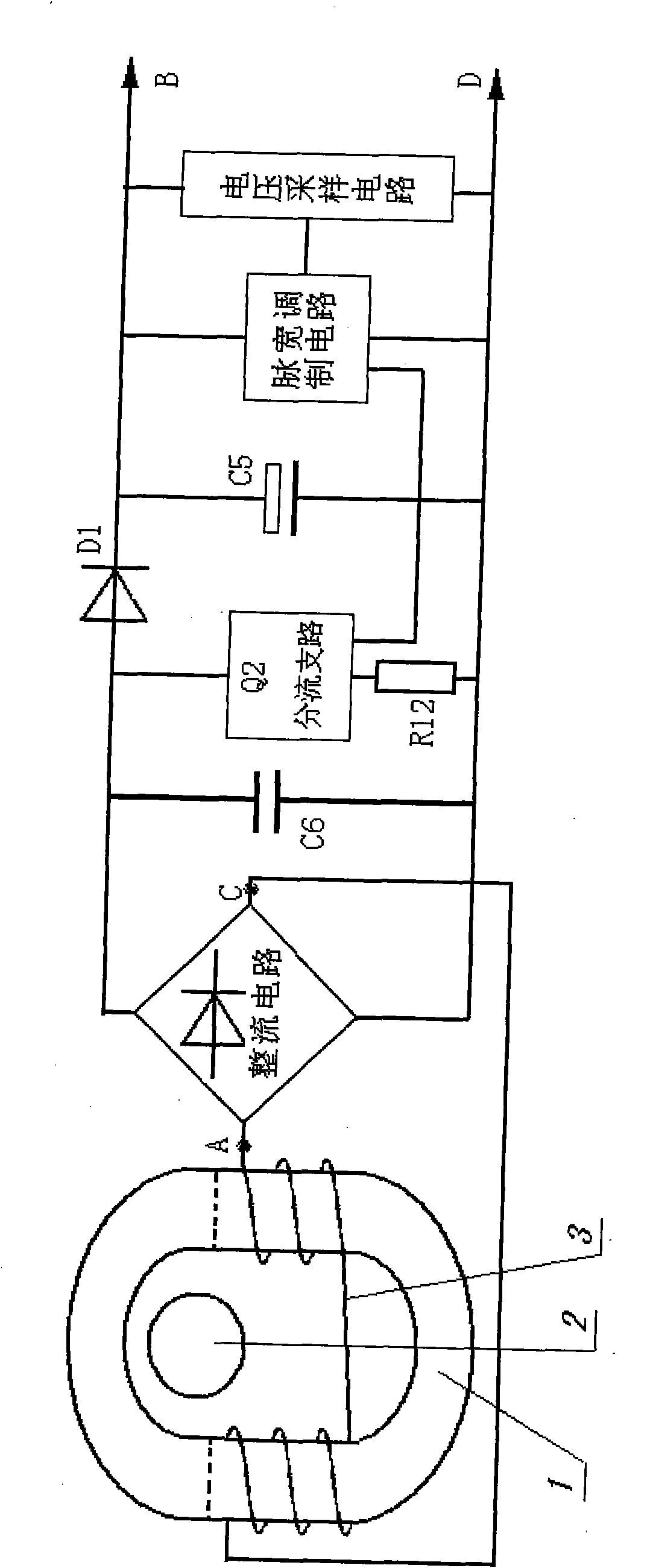
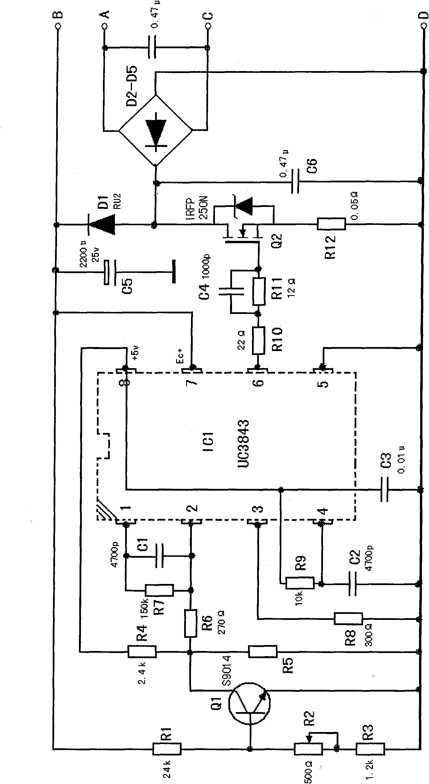
[0019] Such as figure 1 As shown, the induction power-taking device used on the high-voltage transmission line includes an openable and closed ring core 1 for hanging on the high-voltage transmission line 2, a secondary coil 3 wound on the ring core 1, and an output adjustment circuit; the output adjustment circuit includes a rectifier circuit connected to two ends of the AC input terminals A and C and the secondary coil, a pulse width modulation circuit, a voltage sampling circuit, and a shunt branch connected between the two DC output terminals of the rectifier circuit Road, and the positive output line terminal B and the negative output line terminal D; the two DC output terminals of the rectification circuit are connected with a high-frequency filter capacitor C6, and the positive terminal of the DC output terminal of the rectification circuit is isolated from the diode D1 and the positive output line The terminal B is connected, and the negative terminal is connected to ...


PUM


Abstract

The invention relates to the electrotechnical field, in particular to an induction electricity getting device for a high-voltage power transmission line. The invention solves the problem that the application effect of the existing power supply realized through induction electricity getting by using current on the high-voltage power transmission line is not good. The induction electricity getting device comprises a ring iron core, a secondary coil and an output regulation circuit. The output regulation circuit comprises a rectification circuit, a pulse width modulation circuit, a voltage sampling circuit, a current division branch circuit, an anode output line terminal and a cathode output line terminal, wherein the current division branch circuit is formed by a switch-type power device and a resistor connected in series; the anode terminal of the rectification circuit is connected with the anode output line terminal through an isolation diode; and the pulse width modulation circuit and the voltage sampling circuit are connected in parallel between output line terminals. The sampled signal input end of the pulse width modulation circuit is connected with the output end of the voltage sampling circuit. A driving pulse output end is connected with the control end of the switch-type power device. The induction electricity getting device can effectively adjust the electric energy obtained through the induction of the high-voltage power transmission line and can ensure the stability of the electric energy provided to external loads.

Description

technical field [0001] The invention relates to the field of electrical technology, in particular to an induction power-taking device used on a high-voltage transmission line to provide low-voltage power supply for monitoring, monitoring and other equipment installed on the high-voltage transmission line. Background technique [0002] It is often necessary to install some auxiliary equipment for monitoring and monitoring line conditions on high-voltage transmission lines. These equipment need to use lower voltage regulated power supplies, such as 5V, 6V, 12V and other voltages, although these equipment consume less power. It must be big, but the power supply is very inconvenient. [0003] At present, the power supply required for auxiliary equipment on high-voltage transmission lines generally has the following solutions: [0004] 1. Use solar panels, but the solar panels need to be maintained or replaced after working for a period of time, which requires power outages on i...

Claims


Application Information

Patent Timeline
Patent Type & Authority Applications(China)
IPC IPC(8): H02J17/00H02M7/155H02J5/00
Inventor 张俊昌田卫红
Owner 张俊昌
Learn More