Ball inductive switch

A technology of inductive switches and balls, which is applied in the field of switches, can solve the problems of inability to simultaneously switch front, rear, left, and right tilts, inability to switch left and right tilts and front and rear tilts, light scattering, etc., to achieve simple structure, avoid scattering, good conduction effect

Inactive Publication Date: 2010-07-21
朱成辉
View PDF0 Cites 6 Cited by
  • Summary
  • Abstract
  • Description
  • Claims
  • Application Information

AI Technical Summary

Problems solved by technology

[0002] Chinese patent (application number) 01260920.X, 200610078607.7, 02146662.9, the ball sensor switch disclosed in 200610083013.5 has the following types: as figure 1 , figure 2 as shown, figure 1 It is the structural disassembly diagram of the existing ball sensor switch, figure 2 It is a cross-sectional view. The groove of the transmitter and receiver of the product communicates with the chamber is a long channel, so the light emitted by the transmitter is very easy to scatter from the long channel and cause malfunction caused by light refraction; image 3 As shown, the product consists of an inner cylinder and an inner cylinder cover to form a closed chamber. One side of the chamber is cone-shaped, and the corresponding inner cylinder cover on the other side is flat. The switch can only be operated in one direction. Tilt switching, unable to switch left and right tilt and front and rear tilt; Figure 4 As shown, the chamber of its product is designed in a "V" shape, which can only be switched left and right; Figure 5 As shown, the chamber of its product is designed as a cylinder, which can only be switched by inversion; Image 6 As shown, the product’s chamber is designed as a plane shape, which can only be switched from left to right, and the ball is unstable, which is prone to malfunction.
None of the above types can simultaneously switch front, rear, left and right tilts
[0003] It can be seen that the above-mentioned existing ball sensor switch obviously still has certain defects in structure and use.

Method used


Image

  • Ball inductive switch
  • Ball inductive switch
  • Ball inductive switch

Examples


Embodiment Construction

[0036] The present invention will be further described in detail below in conjunction with the accompanying drawings and specific embodiments.

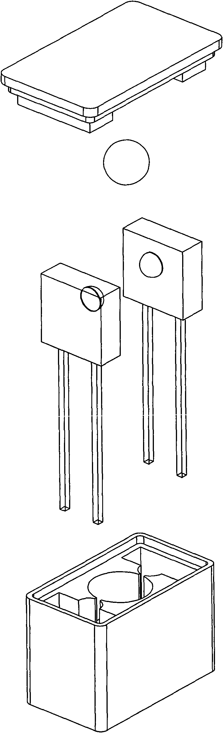
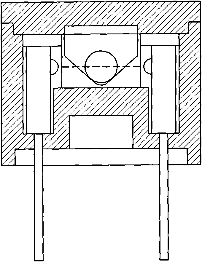
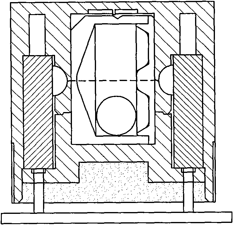
[0037] like Figure 7 to Figure 11 As shown, a ball sensor switch includes a housing 1, a ball 4, a transmitter 2 and a receiver 3, the housing 1 is provided with a chamber 10 for the ball 4 to move, and the transmitter is installed. 2 and the receiving chamber 14 where the receiver 3 is installed, one side of the chamber 10 communicates with the emitting chamber 13, and the other side of the chamber 10 communicates with the receiving chamber 14, and the light beam sent by the transmitter 2 passes through the chamber 10 shoot to the receiver 14 to form a direct communication path 6, the ball 4 switches back and forth between blocking the communication path 6 and breaking away from the communication path 6, the inner wall of the chamber 10 is provided with at least one recessed berth, when the ball 4 When partially sinking into any be...


PUM


Abstract

The invention relates to a ball inductive switch which comprises a shell, a ball, a transmitter and a receiver, wherein an accommodating chamber, a transmitting chamber and a receiving chamber are arranged in the shell; light beams sent from the transmitter are transmitted to the receiver after passing through the accommodating chamber to form a direct communication path; the inner wall of the accommodating chamber is provided with recessed berths. When a ball is sunk in any one berth, the ball is in a stable balance state. The inner wall of the accommodating chamber is provided with three berths which respectively are a first berth, a second berth and a third berth. The first berth and the second berth are respectively a pit. The pit bottom of the first berth is provided with a transmitting port, and the pit bottom of the second berth is provided with a receiving port. The communication path passes through the transmitting port and the receiving port. When the ball rolls into the first berth or the second berth, the ball blocks the communication path; when the third berth is positioned between the first berth and the second berth, and is a circular channel surrounding the communication path. When the ball rolls into the third berth, the ball deviates from the communication path. The invention has the advantages of simple structure, stable signal and good communication.

Description

(1) Technical field [0001] The invention relates to a switch, in particular to a ball induction switch which utilizes a transmitter and a receiver to achieve opening and closing actions and adopts a non-contact conduction mode. This ball sensor switch can avoid light scattering and refraction, and will not cause malfunction. The signal output is stable. When the shell is vertical according to the direction of the arrow, the ball sensor switch can be switched forward, backward, left, right and tilted. . (2) Background technology [0002] Chinese patent (application number) 01260920.X, 200610078607.7, 02146662.9, the ball sensor switch disclosed in 200610083013.5 has the following types: as figure 1 , figure 2 as shown, figure 1 It is the structural disassembly diagram of the existing ball sensor switch, figure 2 It is a cross-sectional view. The groove of the transmitter and receiver of the product communicates with the chamber is a long channel, so the light emitted by...

Claims


Application Information

Patent Timeline
Patent Type & Authority Applications(China)
IPC IPC(8): H03K17/94
Inventor 朱成辉
Owner 朱成辉
Why Eureka
Try Eureka