Non-fusion implantation device between dynamic spinous processes

An implant device and interspinous process technology, which is applied in the field of dynamic interspinous process non-fusion implant devices, can solve the problems of patients with osteoporosis, the stabilizer cannot limit forward flexion, and the limit of backward bending is too large

Inactive Publication Date: 2010-07-28
UNIV OF SHANGHAI FOR SCI & TECH
View PDF6 Cites 11 Cited by
  • Summary
  • Abstract
  • Description
  • Claims
  • Application Information

AI Technical Summary

Problems solved by technology

The Chinese patent with the notification number CN1309549 discloses a device for relieving intervertebral disc-related diseases, which is embedded between two spinous processes, but the device cannot restrict the front bending, and the restriction on the rear bending is too large, and it is not convenient to rotate left and right , did not achieve the purpose of dynamic fixation, and its spacer is not elastic, which will cause complicati

Method used


Image

  • Non-fusion implantation device between dynamic spinous processes
  • Non-fusion implantation device between dynamic spinous processes
  • Non-fusion implantation device between dynamic spinous processes

Examples


Example Embodiment

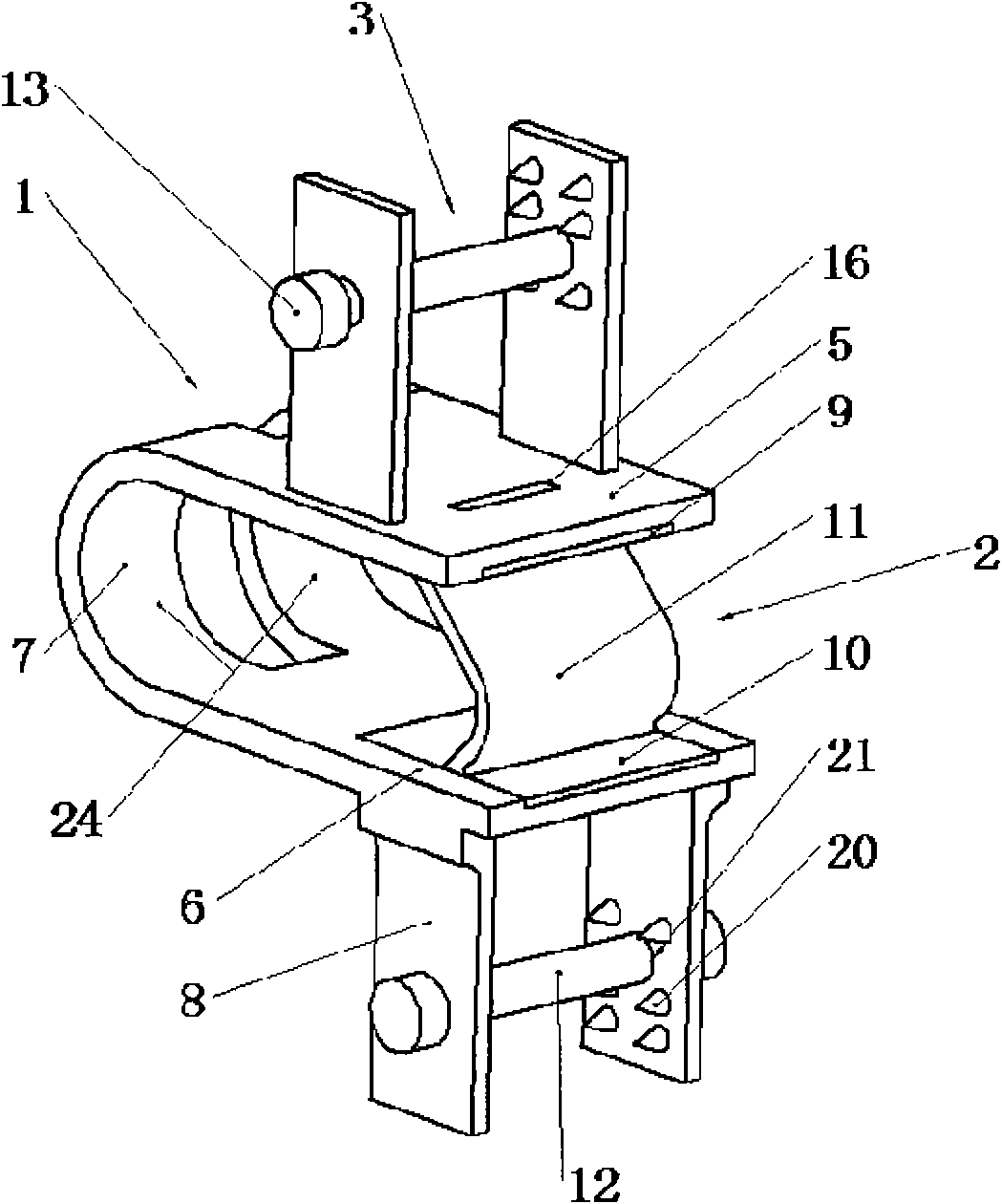
[0041] The present invention provides such an implanting device, which is placed between the spinous processes of adjacent vertebral bodies to stabilize the vertebral bodies. like figure 1 As shown in the embodiment, the implant device includes a central body 1 , an elastic body 2 and a locking device 3 . The central body 1 includes three parts: an upper part 5 , a lower part 6 and a middle part 7 . The upper part 5 includes an upper connection port 16 connected with the elastic body 2 ; similarly, the lower part 6 includes a lower connection port 17 connected with the elastic body 2 . Limiting wings 8 extend from the upper part 5 and the lower part 6 respectively, and the limiting wings 8 include symmetrical wing holes 21 and wing teeth 20 of different shapes.

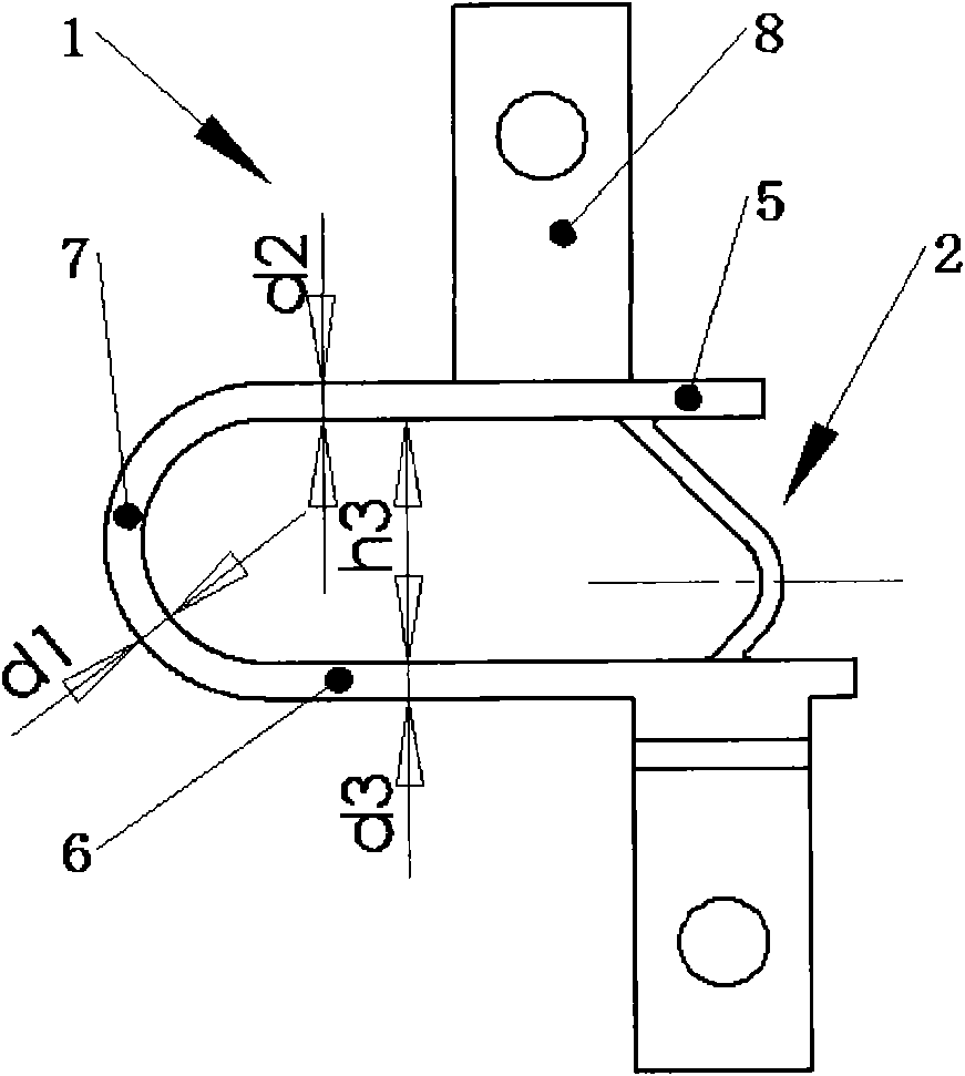
[0042] The upper part 5 of the central body 1, the lower part 6 and the middle part 7 can have different thickness dimensions, such as Figure 2A As shown, d1 is the thickness of the middle part 7, d2 is the thickn...


PUM


Abstract

The invention relates to a non-fusion implantation device between dynamic spinous processes, belonging to the technical field of spinal column surgical medical instruments and aiming to provide an implant combined type or signal type device for treating or remitting diseases related to a spinal column. The implantation device is embedded between two spinous processes and comprises a center body, two limited wings and a locking device, wherein the center body is a flexible body, is integrally in a U shape and comprises three parts, i.e. an upper part, a middle part and a lower part, and the upper part and the lower part of the center body are provided with areas which are implanted between the spinous processes and contact with the spinous processes; the limited wings extend from the center body to the spinous processes; and the locking device is used for fixing the limited wings and the spinous processes. The non-fusion implantation device provides the dynamic fixing of anteflexion, retroflexion, left rotation and right rotation without generating adjacent segment degeneration acceleration or novel syndromes and can be widely suitable for treating and remitting the diseases related to the spinal column or osteoporosis diseases.

Description

technical field [0001] The invention relates to the technical field of spinal surgery medical instruments, in particular to a dynamic non-fusion implantation device between spinous processes. Background technique [0002] Traditional spinal diseases, except for traumatic fractures, are mostly caused by atrophy of intervertebral discs, resulting in narrowing of the intervertebral space and compression of the spinal nerve foramen, resulting in numbness or pain. At present, the most commonly used treatment method is to apply pedicle screw technology or fusion cage technology to perform fusion surgery on the lesion. The principles of these technologies are all spinal fusion techniques, that is, with the diseased intervertebral disc as the center, fusion is performed between the previous vertebral body and the next vertebral body of the diseased body, and finally the two vertebral bodies become a whole. The advantages of this technique are: immediate stability, immediate disappe...

Claims


Application Information

Patent Timeline
IPC IPC(8): A61B17/70
CPCA61B17/7062
Inventor 谷雪莲李雷于颖冯勇
Owner UNIV OF SHANGHAI FOR SCI & TECH
Why Eureka
Try Eureka