Electric vehicle deceleration and differential integrated rear axle assembly
What is Al technical title?
Al technical title is built by PatSnap Al team. It summarizes the technical point description of the patent document.
A technology for electric vehicles and rear axles, applied in vehicle components, control devices, transportation and packaging, etc., can solve the problems of large friction loss of parts, large output power loss, and high vehicle repair rate, and achieve low output power loss. , Reduce the friction loss of transmission, the effect of smooth transmission
Inactive Publication Date: 2010-07-28
薛建南
View PDF4 Cites 14 Cited by
Summary
Abstract
Description
Claims
Application Information
AI Technical Summary
This helps you quickly interpret patents by identifying the three key elements:
Problems solved by technology
Method used
Benefits of technology
Problems solved by technology
[0002] The current commercially available electric vehicle transmission system is a part of the transmission of the motor, the transmission output shaft passes through the sprocket, the chain, the intermediate transmission shaft, the intermediate transition sprocket, and the transmission chain, and is transmitted to the rear axle to drive the rear wheel drive shaft through the secondary transmission. , to drive electric vehicles, there are the following disadvantages: through the secondary transmission, it is necessary to increase transmission components such as sprockets, chains, intermediate transition transmission shafts, and intermediate transition sprockets to drive the rear wheel drive shaft, the manufacturing cost is high, and the parts in the transmission process The friction loss is large, the transmission chain is easy to fall off the sprocket, the output power loss is large, the maintenance is troublesome, and the repair rate of the whole vehicle is high
Method used
Image
Click on the blue label to locate the original text in one second.
Reading with bidirectional positioning of images and text.
Examples
Embodiment Construction
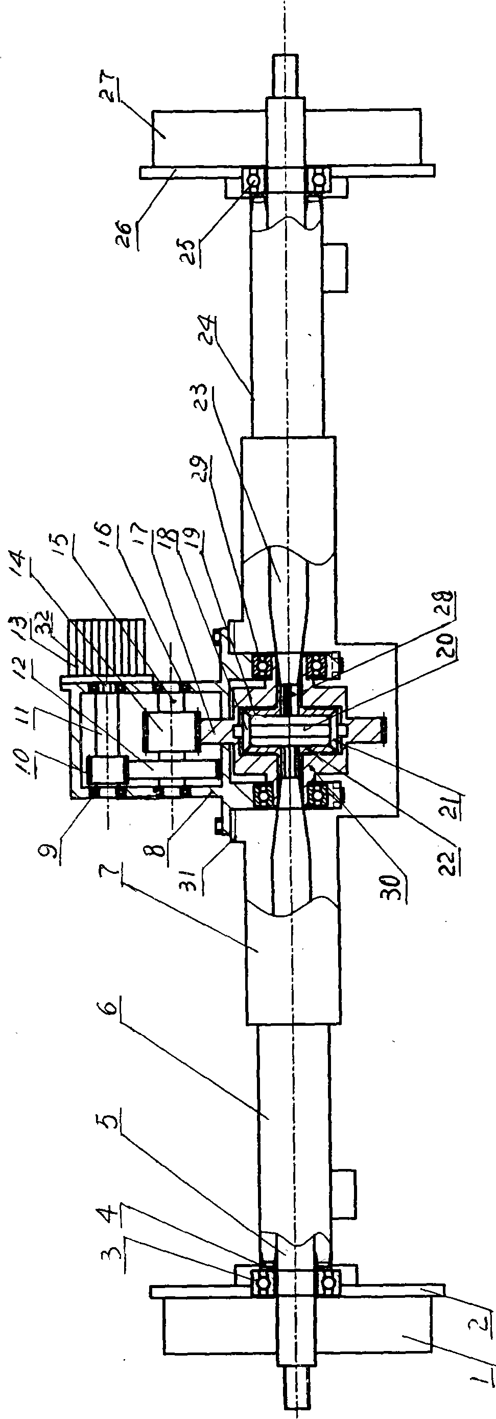
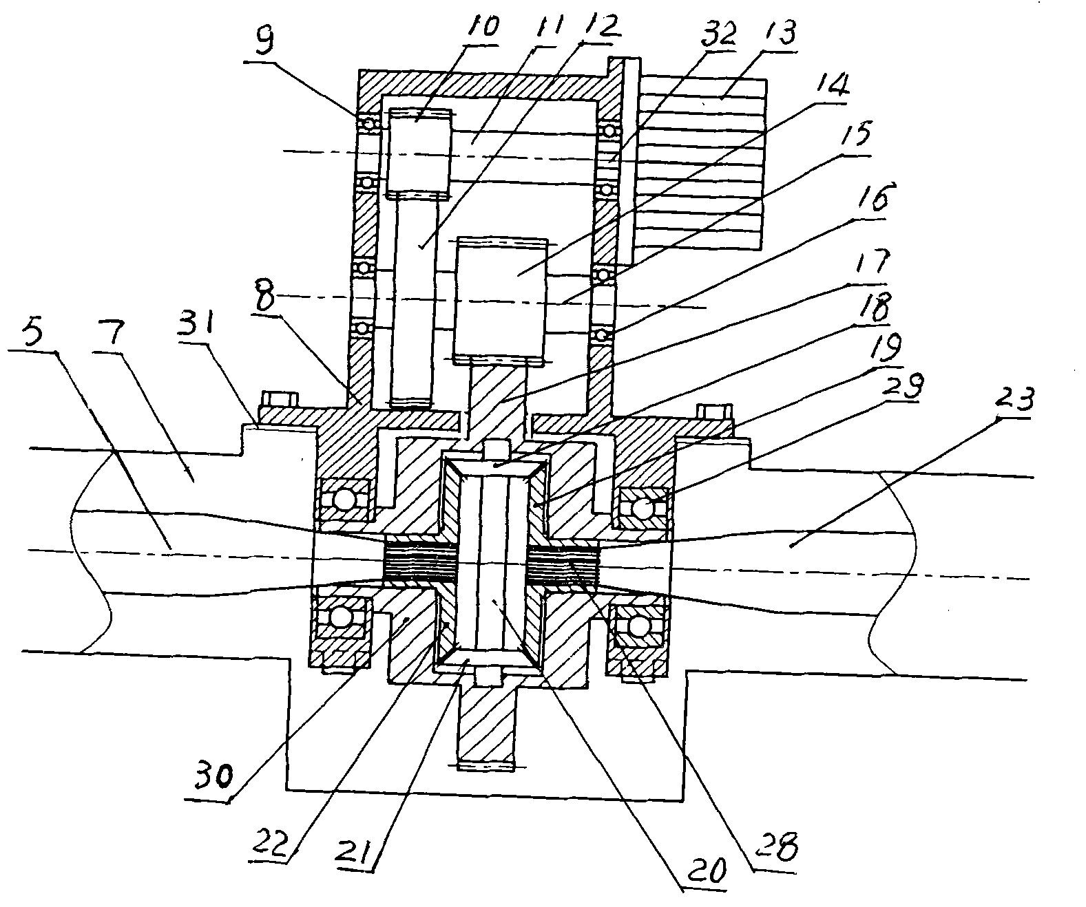
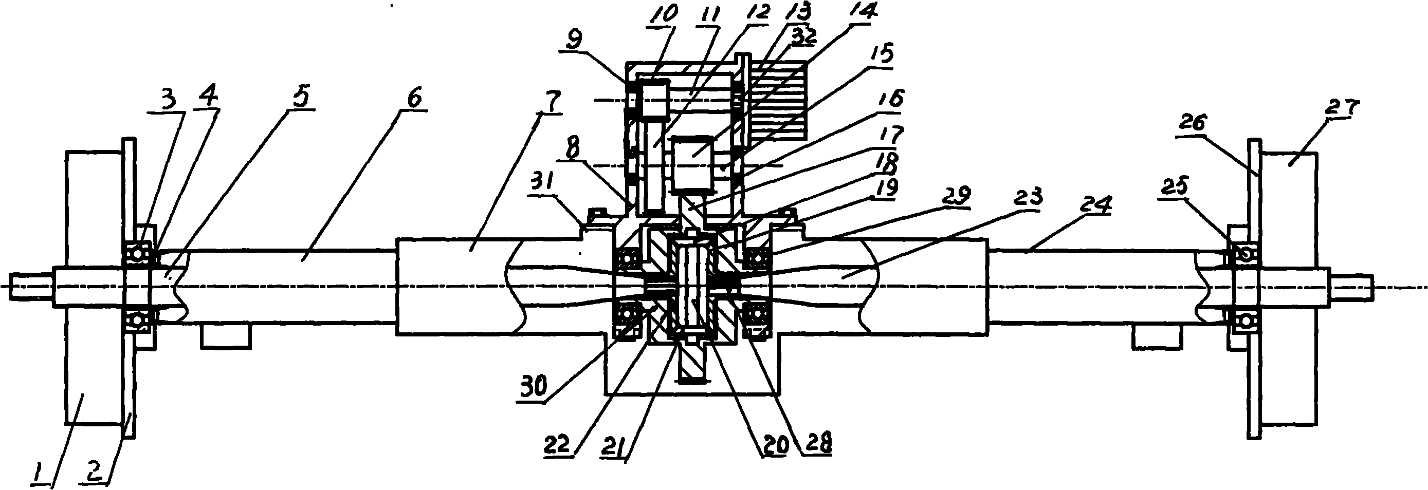
[0017] Refer to attached figure 1 , 2 , Electric vehicle deceleration, differential integrated rear axle assembly is made up of motor 13, speed reducer, differential, deceleration differential casing 8 and rear axle.
[0018] Rear axle comprises rear axle frame 7, axle shaft one 5, axle shaft two 23, brake fixing plate one 2, brake fixing plate two 26, brake block, brake cam, wheel hub one 1 and wheel hub two 27. Bridge tube one 6 and bridge tube two 24 are respectively arranged at rear bridge frame 7 both sides, and brake fixing plate one 2 is housed in bridge tube one 6 outsides, and brake fixing plate two 27 is housed in bridge tube two 24 outsides. Described brake fixed plate one 2 and brake fixed plate two 27 are equipped with two brake blocks, and two brake blocks are contained on the brake fixed plate by brake positioning pins, and brake projection is housed between two brake blocks. Half shaft one 5 and half shaft two 23 are provided with splines 28 at one end, half ...
PUM
Abstract
The invention relates to an electric vehicle reduction and differentiation integrated rear axle assembly which is an integrated assembly of a motor, a reducing mechanism, a differential mechanism and a rear axle of an electric vehicle. The integrated assembly is applied to rear axle drive systems of freight vehicles, passenger vehicles, electric three-wheeled vehicles, electric four-wheeled vehicles and the like. The integrated assembly comprises the motor, the reducing mechanism, the differential mechanism, a reduction and differential case and the rear axle. The rear axle comprises a rear axle stand, a first drive half-axle, a second drive half-axle, a first braking fixed plate, a second braking fixed plate, a brake block, a brake cam, a first hub and a second hub. The reduction and differential case is installed on the rear axle stand and is fixed by screws; the reducing mechanism comprises a reducing gear shaft, a reduction transition gear and a reduction transition pinion; and the differential mechanism comprises a differential mechanism housing, a differential gear, a first satellite gear, a second satellite gear, a satellite gear shaft, a first spline gear, a second spline gear and a fifth bearing. The differential mechanism housing is installed below the reduction and differential case through the fifth bearing and a bearing support, and the differential gear is arranged outside the differential mechanism housing.
Description
technical field [0001] The electric vehicle deceleration and differential integrated rear axle assembly of the present invention relates to an electric vehicle motor, reducer, differential, and rear axle integrated assembly, which is suitable for freight, passenger transport, electric three-wheel and electric four-wheel Cars and other rear axle drive systems. Background technique [0002] The current commercially available electric vehicle transmission system is a part of the transmission of the motor, the transmission output shaft passes through the sprocket, the chain, the intermediate transmission shaft, the intermediate transition sprocket, and the transmission chain, and is transmitted to the rear axle to drive the rear wheel drive shaft through the secondary transmission. , to drive electric vehicles, there are the following disadvantages: through the secondary transmission, it is necessary to increase transmission components such as sprockets, chains, intermediate tra...
Claims
Application Information
Patent Timeline
Application Date:The date an application was filed.
Publication Date:The date a patent or application was officially published.
First Publication Date:The earliest publication date of a patent with the same application number.
Issue Date:Publication date of the patent grant document.
PCT Entry Date:The Entry date of PCT National Phase.
Estimated Expiry Date:The statutory expiry date of a patent right according to the Patent Law, and it is the longest term of protection that the patent right can achieve without the termination of the patent right due to other reasons(Term extension factor has been taken into account ).
Invalid Date:Actual expiry date is based on effective date or publication date of legal transaction data of invalid patent.