Method for assembling cable built-in fiber bragg grating strain transducer

A strain sensor and fiber grating technology, applied in the field of cable load-bearing structures, can solve problems such as cable damage, achieve the effect of ensuring survival rate, ensuring reliability and long-term stability, and solving process difficulties

Active Publication Date: 2010-07-28
法尔胜集团有限公司 +1
View PDF1 Cites 10 Cited by
  • Summary
  • Abstract
  • Description
  • Claims
  • Application Information

AI Technical Summary

Problems solved by technology

However, due to structural design, environmental corrosion and fatigue accumulation, it is

Method used


Image

  • Method for assembling cable built-in fiber bragg grating strain transducer
  • Method for assembling cable built-in fiber bragg grating strain transducer
  • Method for assembling cable built-in fiber bragg grating strain transducer

Examples


Embodiment Construction

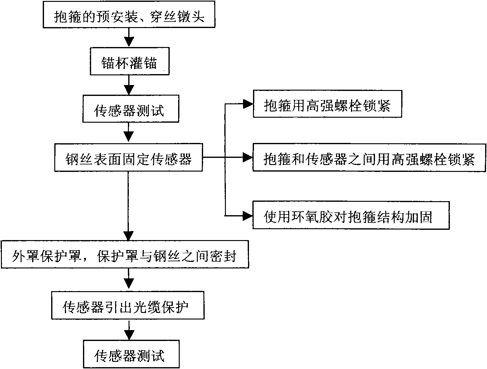
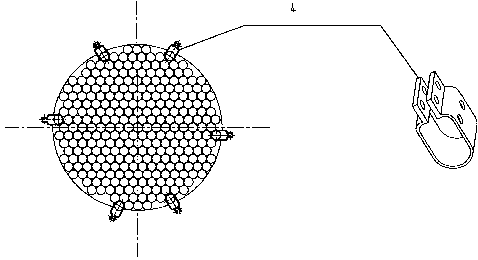
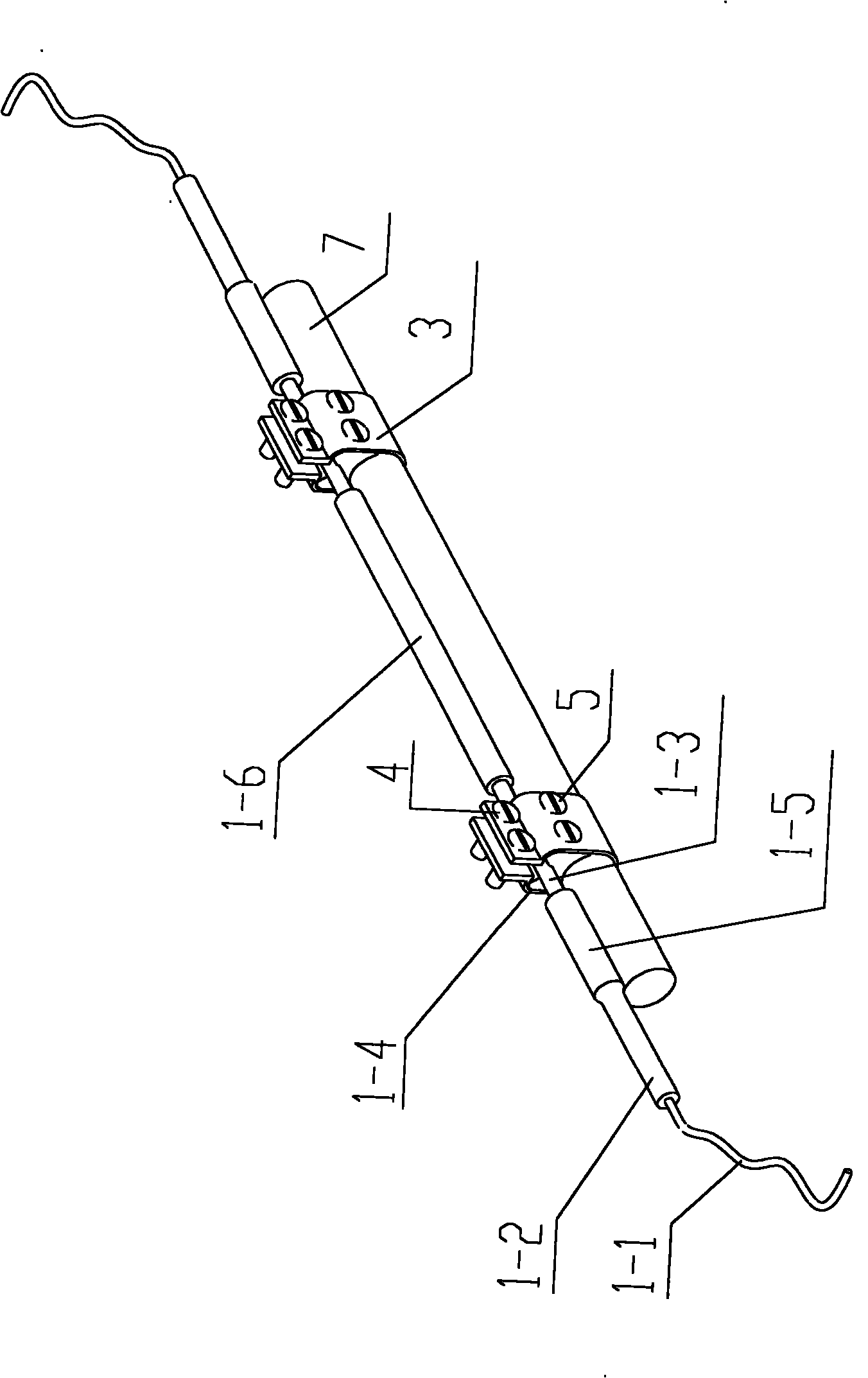
[0029] The installation process of the fiber grating strain sensor 1 in the cable is as follows: figure 1 shown. Before the wire threading and heading process of the cable, the hoop 3 is threaded on the peripheral steel wire 7 of the cable connecting cylinder where the fiber grating strain sensor 1 is to be installed, and two steel wires are installed on each steel wire. The pre-installation of the hoop 3 is completed. Such as figure 2 shown. After the cable filling and anchoring process is completed, the fiber grating strain sensor 1 is connected to a special instrument for testing to ensure that the sensor is intact. In the area of ​​the cable connecting cylinder 6, after cleaning the surface of the peripheral steel wire 7 of the cable connecting cylinder where the optical fiber grating strain sensor 1 is to be arranged, fix the optical fiber grating strain sensor 1 to the surface of the peripheral steel wire 7 of the cable connecting cylinder with a hoop 3 , the hoop 3...


PUM


Abstract

The invention relates to a method for assembling a cable built-in fiber bragg grating strain transducer. The method comprises the following technical processes of: sleeving a hoop onto a peripheral steel wire of a cable connecting cylinder place to be assembled with the fiber bragg grating strain transducer before working procedures of feeding and heading the cable to complete preassembly of the hoop; fixing the fiber bragg grating strain transducer on the surface of the peripheral steel wire of the cable connecting cylinder place with the hoop in the area of a cable connecting cylinder after finishing the working procedure of anchoring the cable; adding a transducer protection cover to protect the fiber bragg grating strain transducer fixed on the surface of the peripheral steel wire of the cable connecting cylinder place after fixing the fiber bragg grating strain transducer, and sealing gaps among the transducer protection cover and the peripheral steel wire of the cable connecting cylinder place; and penetrating a tail cable of the fiber bragg grating strain transducer into a reserved steel tube channel arranged in the cable connecting cylinder and a socket, and protecting the joint of the tail cable and the reserved steel tube with a heat-shrinkable bush in a hot shrinkage way. The method effectively ensures reliability and long-term stability of intelligent cabling operation.

Description

(1) Technical field [0001] The invention relates to an installation method for installing a fiber grating strain sensor inside a cable, which is suitable for cable load-bearing structures such as cable-stayed bridges, suspension bridges, and arch bridges. (2) Background technology [0002] The cable system of modern long-span bridges is the core component of cable-stayed bridges and suspension bridges. Most of the self-weight and dynamic load on the bridge structure of long-span bridges are transmitted to the tower columns through the cable system, and the working status of the cables is a direct reflection. One of the important symbols of whether the bridge is in a safe state. However, due to structural design, environmental corrosion and fatigue accumulation, it is inevitable that cables will be damaged and deteriorated to varying degrees during service. If the sensor can be organically integrated into the cable, so that it can measure parameters such as internal stress a...

Claims


Application Information

Patent Timeline
IPC IPC(8): E01D19/16
CPCD07B1/145D07B2501/203D07B2301/5577D07B2301/259
Inventor 刘礼华赵霞姜德生李盛薛花娟周祝兵周明宝吉俊兵张恩隆王利明
Owner 法尔胜集团有限公司
Why Eureka
Try Eureka