Multi-impingement-surface for cooling a wall

A technology of composite structure and cooling fluid, applied in the direction of supporting elements of blades, combustion methods, manufacturing converters, etc., can solve problems such as incapable of precision manufacturing, and achieve the effect of optimizing pressure loss

Inactive Publication Date: 2010-07-28
SIEMENS AG
View PDF8 Cites 3 Cited by
  • Summary
  • Abstract
  • Description
  • Claims
  • Application Information

AI Technical Summary

Problems solved by technology

The problem is that conventionally said porous struct

Method used


Image

  • Multi-impingement-surface for cooling a wall
  • Multi-impingement-surface for cooling a wall
  • Multi-impingement-surface for cooling a wall

Examples


Embodiment Construction

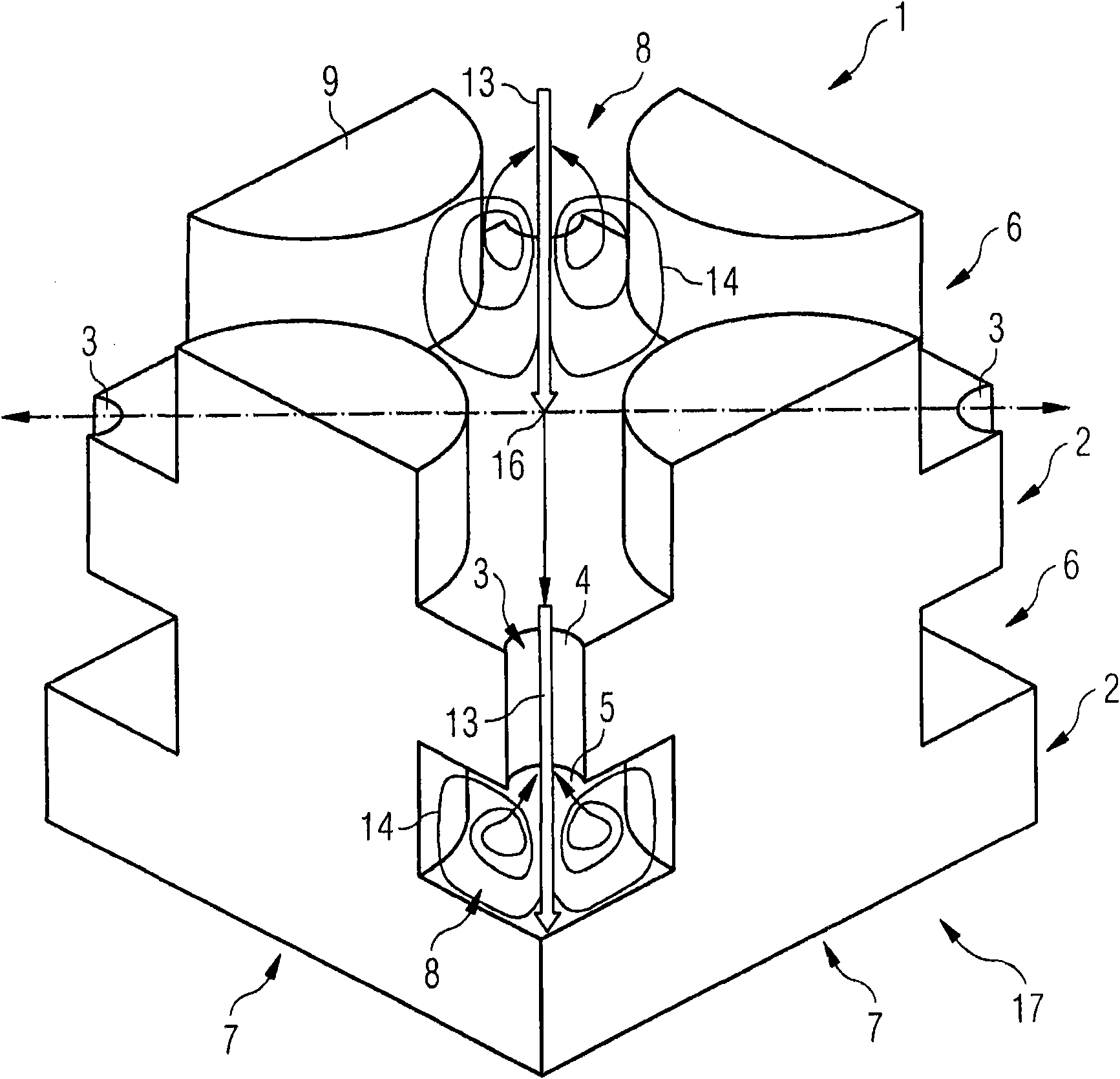
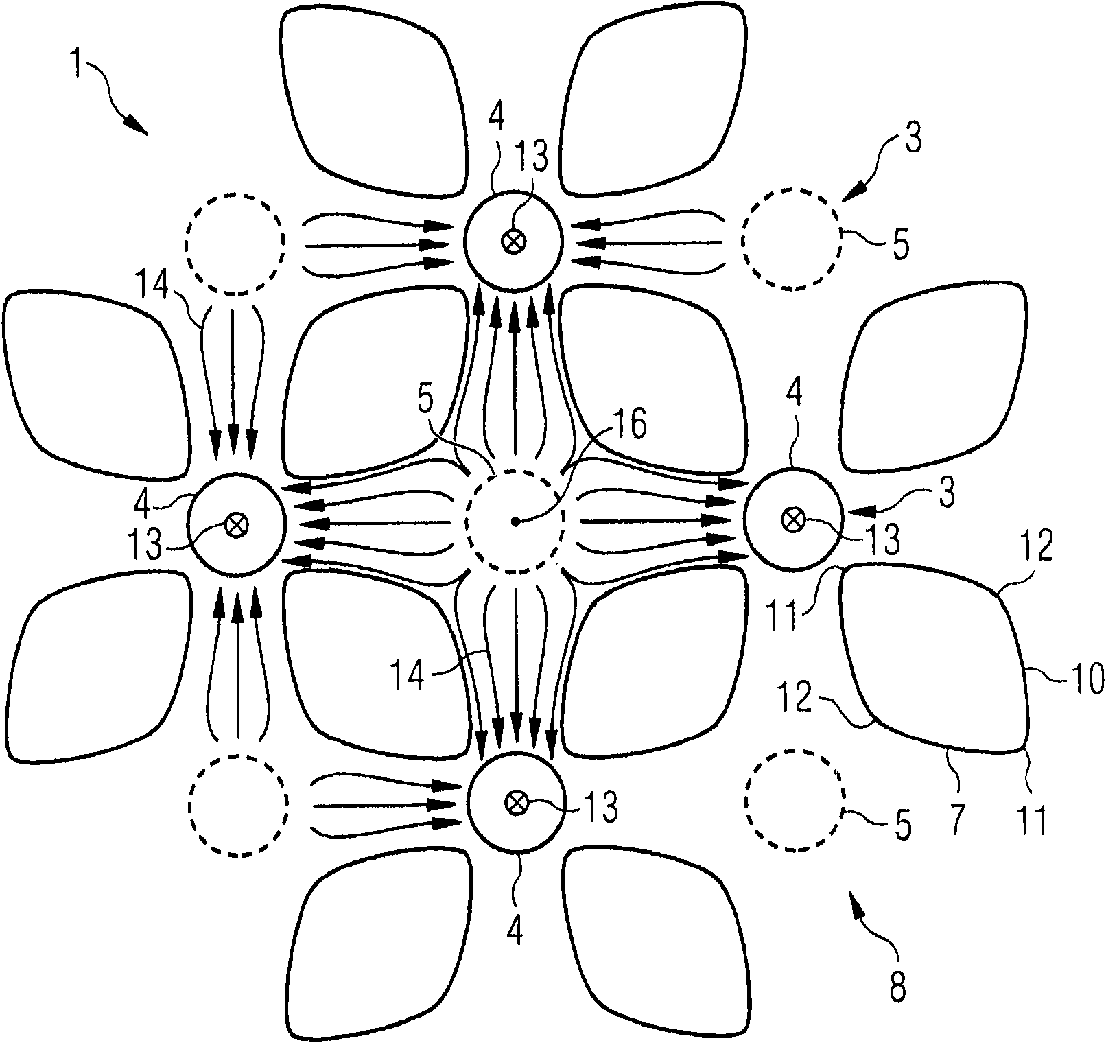
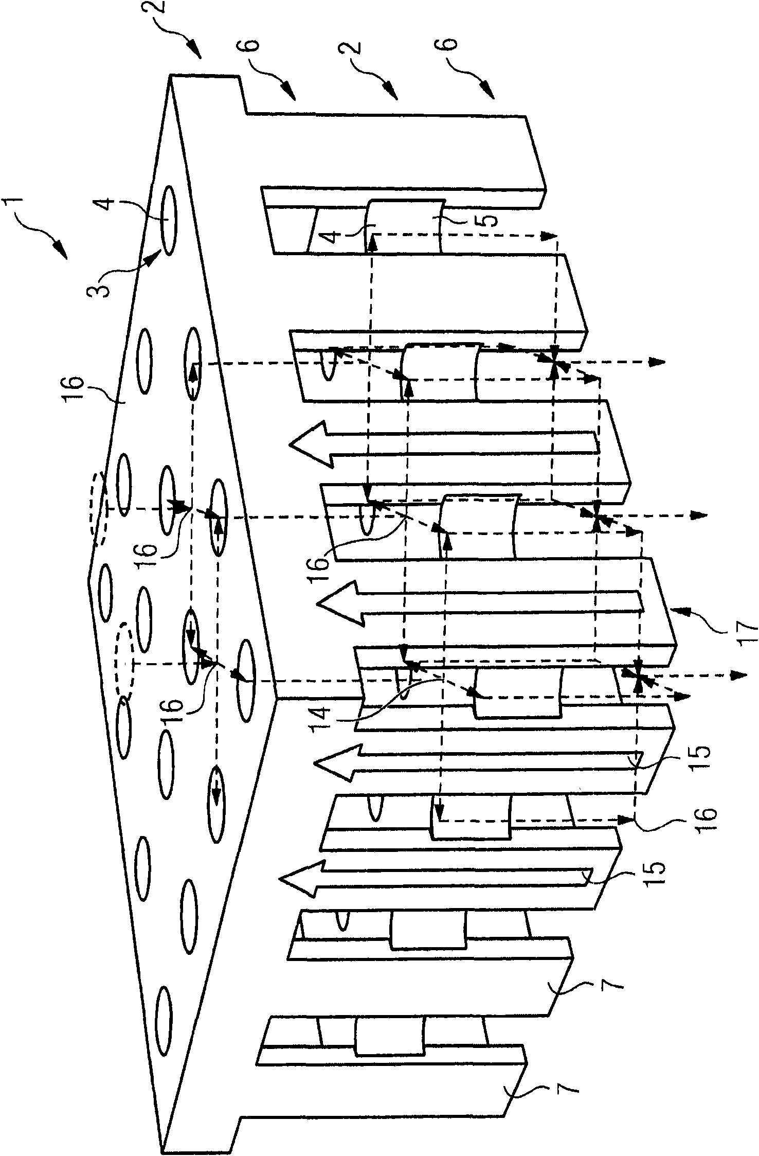
[0026] as available from Figures 1 to 3 It can be seen from the figure that the multi-impact composite structure has a plurality of orifice layers 2 in which a plurality of through-holes 3 are arranged in the form of a grid. The cooling fluid flows through the through-holes 2 , which thus each have an inflow side 4 and an outflow side 5 .

[0027] In addition, the multi-impact composite structure 1 has a plurality of web layers 6, which are respectively arranged between two adjacent perforated plate layers 2, so that the multi-impact composite structure 1 has Sandwich structure composed of layer 2 and tab layer 4. The web layer 6 is formed from a plurality of webs 7 which, like the through-holes 3 , are likewise arranged in a grid-like manner and with their longitudinal direction perpendicular to the perforated plate layer 2 . Each web 7 thus bridges the distance between two adjacent orifice layers 2 , so that heat can be transferred from one orifice layer 2 to the other vi...


PUM


Abstract

The invention relates to a multi-impingement-surface for cooling a wall, capable of planedly and conductively contacting with the surface of a wall to be cooled and comprising a plurality of pore plate surfaces and a plurality of splicing surfaces. The pore plate surfaces comprises a plurality of straight through holes as the pore plate constructions distributed on the surface of the pore plate surfaces and the splicing surfaces and the pore plate surfaces are alternatively stacked and the slicing plates are distributed on the surface of the pore plate layer and correspondingly spliced with the pore plate layer, wherein each splice of one splicing layer is respectively aligned with one of the splice of other splicing layers and each straight through hole of one pore plate layer is staggered relative to the other straight through hole of the adjacent pore plate layer, therefore the multi-impingement-surface is loaded by the pressure using a cooling fluid at a flat side and the cooling fluid flows through the straight through hole and the middle clearance between the splice and the pore plate layer and thus the heat flow from the wall is discharged along with the cold flow.

Description

technical field [0001] The invention relates to a multi-impact composite structure for cooling a wall, a wall with a multi-impact composite structure and a method for producing the multi-impact composite structure. Background technique [0002] In internal combustion engines, in particular gas turbines, high operating temperatures exist, so that the hot gas-conducting components are subjected to high thermal loads. If the hot gas reaches a temperature above the maximum permissible operating temperature of the hot gas-carrying component during operation of the gas turbine, the hot gas-carrying component should be cooled so that it is not damaged. Conventionally, in gas turbines, the cooling air branched off from the compressor of the gas turbine is used to cool the hot gas-carrying components. As a result, the efficiency of the gas turbine is reduced, so that the cooling air consumption should be as low as possible, so that the cooling air should be used as efficiently as po...

Claims


Application Information

Patent Timeline
IPC IPC(8): F01D25/12
CPCF23M5/00F23R2900/03044F01D5/184C21C5/4646F23R3/002F28F3/02F05D2250/185F01D5/183F28D2021/0078B22F7/064B22F7/08
Inventor A·赫塞尔豪斯
Owner SIEMENS AG
Why Eureka
Try Eureka