Pressure-bearing contact type shaft seal ring

A sealing ring and contact technology, which is applied to the sealing of the engine, engine components, mechanical equipment, etc., can solve the problems of loss of sealing performance and degradation of sealing performance, and achieve the effects of preventing leakage, strengthening sealing performance, and simple manufacture

Inactive Publication Date: 2012-05-30
谢晓山 +1
View PDF1 Cites 0 Cited by
  • Summary
  • Abstract
  • Description
  • Claims
  • Application Information

AI Technical Summary

Problems solved by technology

[0002] In order to provide a sealing ring with good sealing performance, long service life and compact structure, Chinese Patent No. ZL200810073588.8 discloses a rolling bearing end face sealing ring, which is composed of inner and outer metal skeletons, disc-shaped metal springs and sealing rings. The sealing ring made of hard material is pressed against the end face of the rolling bearing to realize the sealing function under the action of the metal spring. When it is large, the sealing performance will be lost

Method used


Image

  • Pressure-bearing contact type shaft seal ring
  • Pressure-bearing contact type shaft seal ring
  • Pressure-bearing contact type shaft seal ring

Examples


Embodiment 1

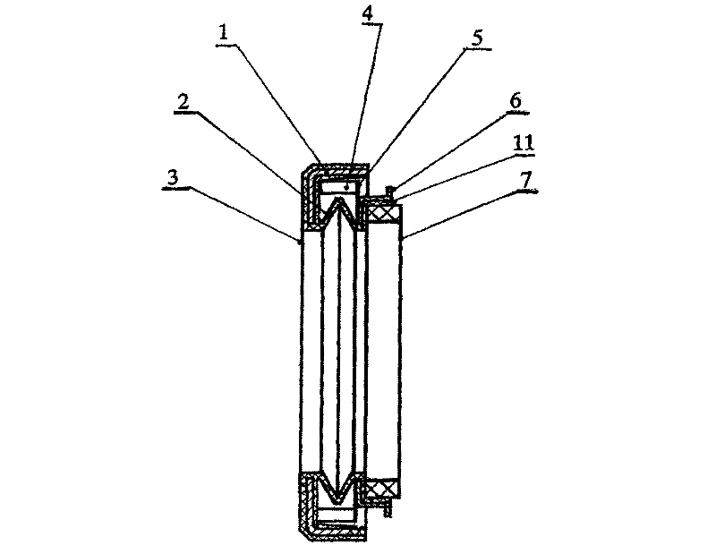
[0020] refer to figure 1 , a pressure-contact shaft seal ring, comprising an outer ring metal skeleton 1, a seal ring main body 3 made of elastomer material, an inner ring metal skeleton 6 and a seal ring 7, and the metal skeleton 1 of the outer ring and the seal ring main body 3 An M-shaped corrugated structural section 2 is arranged between the central inner rings 11, an inner ring metal skeleton 6 is installed on the outer diameter of the central inner ring 11, and an annular toothed spring 5 is installed on the end surface of the inner ring metal skeleton 6, and the central inner ring Sealing ring 7 is installed in the internal diameter of 11.

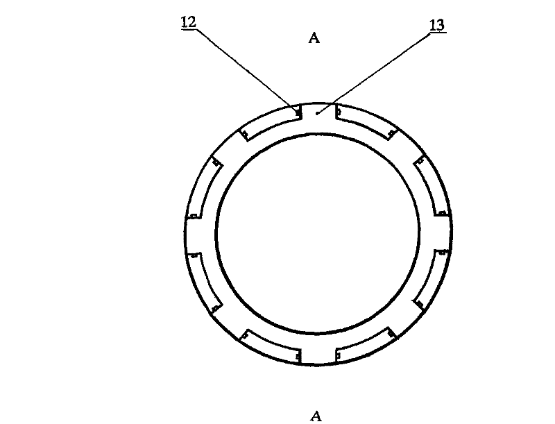
[0021] refer to image 3 Figure 4 , two ends of the combined stepped outer ring metal frame 8 are processed with grooved steps, and the pressure retaining ring 13 is processed with inner holes and outer teeth, and its outer teeth are embedded in the groove at one end of the combined stepped outer ring metal frame 8 The riveting...

Embodiment 2

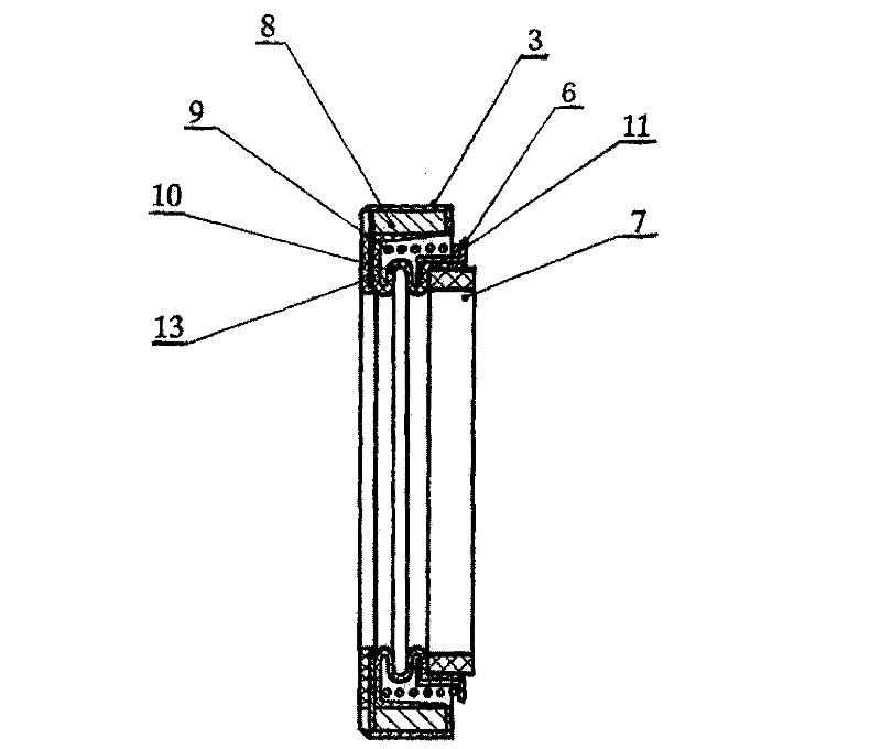
[0025] refer to figure 2 image 3 Figure 4 Another structural form of the pressure-bearing contact shaft seal ring of the present invention includes a seal ring main body 3 made of elastomer material, a combined stepped outer ring metal skeleton 8 and a seal ring 7, and the combined stepped metal skeleton 8 There is an S-shaped corrugated structural section 10 between the central inner ring 11 of the sealing ring main body 3, and the sealing ring main body 3 made of elastomer material wraps the combined stepped outer ring metal skeleton 8 and the pressure ring 13 riveted with it 1. The S-shaped corrugated structure section 10 continues to extend to the central inner ring 11 to form a whole, and a cylindrical spring 9 is installed on the outer flange end face of the inner ring metal skeleton 6 or an annular warping tooth is installed on the inner flange end face Spring, the sealing ring 7 is installed in the center inner ring 11.

[0026] The metal frame 8 of the combined ...


PUM


Abstract

The invention discloses a pressure-bearing contact type shaft seal ring which comprises an outer ring metal framework, an inner ring metal framework, a seal ring main body and a seal ring, wherein the seal ring main body is made of an elastomeric material. The pressure-bearing contact type shaft seal ring is characterized in that a corrugated structural segment is arranged between the outer ring metal framework and a central inner ring, an annular raised-tooth spring is installed on the end surface of an inner flange of the inner ring metal framework or a cylindrical spring is installed on the end surface of an outer flange, the seal ring or a combined seal ring is installed in the central inner ring of the seal ring main body, and the corrugated structural segment is an M-shaped corrugated structural segment or an S-shaped corrugated structural segment. The seal ring still has good sealing performance under a pressure environment and also has simple manufacture, easy installation andlong working and use life.

Description

technical field [0001] The invention relates to a sealing element for shafts in mechanical manufacturing, in particular to a pressure-bearing contact type shaft sealing ring. Background technique [0002] In order to provide a sealing ring with good sealing performance, long service life and compact structure, Chinese Patent No. ZL200810073588.8 discloses a rolling bearing end face sealing ring, which is composed of inner and outer metal skeletons, disc-shaped metal springs and sealing rings. The sealing ring made of hard material is pressed against the end face of the rolling bearing to realize the sealing function under the action of the metal spring, but the disadvantage is that when there is a negative pressure difference between the external environment and the sealed container, the sealing performance will decrease and the pressure difference will be too high When it is large, the sealing performance will be lost. Contents of the invention [0003] The purpose of th...

Claims


Application Information

Patent Timeline
Patent Type & Authority Patents(China)
IPC IPC(8): F16J15/34
Inventor 谢晓山李雄
Owner 谢晓山
Why Eureka
Try Eureka