Limit filling device used for cryogenic liquid container and cryogenic liquid container

A low-temperature liquid and container technology, applied in the field of limit filling device and low-temperature liquid container, can solve the problems of low-temperature steam and liquid discharge, environmental pollution, low-temperature liquid waste, etc., to achieve safe filling process, avoid environmental pollution, and save energy energy effect

Active Publication Date: 2010-07-28
NANTONG CIMC TANK EQUIP CO LTD
View PDF0 Cites 5 Cited by
  • Summary
  • Abstract
  • Description
  • Claims
  • Application Information

AI Technical Summary

Problems solved by technology

[0006] Based on the above, the existing problems in the filling technology of cryogenic liquid containers are as follows: first, there is low-temperature gas emission during the filling process, causing environmental pollution and waste of low-temperature liquid; second, when the filling process is full, the , low-temperature liquid flows out, causing waste of low-temperature liquid and polluting the environment; third, during the filling process and after filling, the staff needs to concentrate on the operation and close the relevant valves in time, which is less humane; fourth, there is low-temperature steam And liquid discharge, unsafe; Fifth, if the full-measurement valve, that is, the liquid discharge valve is forgotten to open, it may cause overfilling, and if the safe liquid level of the low-temperature liquid container is exceeded, it may cause the danger of pressure suppression and tank explosion
Therefore, the cryogenic liquid filling technology of existing cryogenic liquid container obviously has inconvenience and defect in actual use, so it is necessary to improve

Method used


Image

  • Limit filling device used for cryogenic liquid container and cryogenic liquid container
  • Limit filling device used for cryogenic liquid container and cryogenic liquid container
  • Limit filling device used for cryogenic liquid container and cryogenic liquid container

Examples


Embodiment Construction

[0024] In order to make the objectives, technical solutions, and advantages of the present invention clearer, the following further describes the present invention in detail with reference to the accompanying drawings and embodiments. It should be understood that the specific embodiments described herein are only used to explain the present invention, but not to limit the present invention.

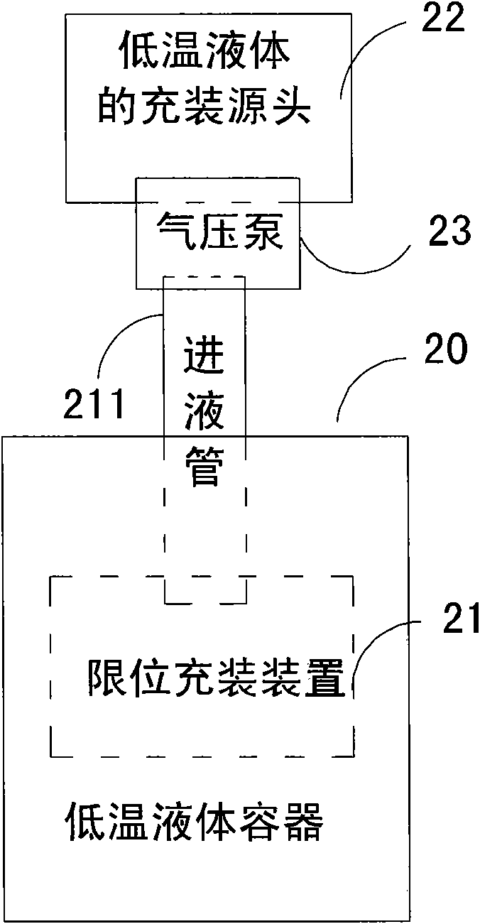
[0025] figure 2 It is a schematic diagram of the filling structure of the cryogenic liquid container of the present invention. The cryogenic liquid container 20 includes a liquid inlet pipe 211 and a limit filling device 21 arranged in the cryogenic liquid container 20. The limit filling device 21 is used to achieve low temperature The non-destructive filling of the liquid in the cryogenic liquid container 20. One end of the liquid inlet pipe 211 is inserted into the cryogenic liquid container 20, and the other end is connected to a pneumatic pump 23. The pneumatic pump 23 is set at the fil...


PUM


Abstract

The invention discloses a limit filling device used for a cryogenic liquid container. The limit filling device is arranged in the cryogenic liquid container and comprises a guide cylinder, a plurality of openings, a cover body, a plurality of small holes and a floater, wherein the guide cylinder is provided with an inner chamber and a first through hole and is positioned at bottom; the openings are positioned at the wall part; the cover body is used for covering the top end of the guide cylinder and is provided with a second through hole used for liquid charging; the small holes are positioned at the wall part of the second through hole; and the floater can be kept in the inner chamber of the guide cylinder. Correspondingly, the invention also discloses the cryogenic liquid container provided with the limit filling device. Therefore, the invention can ensure the safety and the continued filling in the filling process of cryogenic liquid and avoid the escape of the cryogenic liquid; in addition, the invention can save energy and protect environment.

Description

Technical field [0001] The invention relates to a cryogenic liquid container, in particular to a limit filling device for a cryogenic liquid container and a cryogenic liquid container. Background technique [0002] Low temperature media commonly used in industry, such as liquid oxygen, liquid nitrogen, liquid argon, LNG (Liquefied Natural Gas), etc., have low temperatures, so the current containers for cryogenic liquids usually consist of two layers of containers inside and outside, and the interlayer adopts vacuum insulation. It is used to reduce the heat leakage of the environment to the cryogenic liquid, so that the cryogenic liquid is kept low during storage and transportation. [0003] Since the temperature of cryogenic liquid is low, taking liquid nitrogen as an example, the working temperature is usually around -196℃. Because of its continuous vaporization during the filling process, the pressure in the tank increases, such as figure 1 As shown, all the usual filling of the ...

Claims


Application Information

Patent Timeline
IPC IPC(8): F17C5/04F17C6/00F17C1/00F17C3/00F17C13/06
Inventor 蒋平安邓明华王坤杨阳
Owner NANTONG CIMC TANK EQUIP CO LTD
Why Eureka
Try Eureka