
New air heat-exchange system for building

A heat exchange system and fresh air technology, applied in ventilation systems, buildings, building components, etc., can solve the problems of aggravated noise, poor heat exchange effect, and high cost, and achieve the effect of simple structure, low noise, and low cost

Inactive Publication Date: 2010-07-28
钟粤
View PDF0 Cites 4 Cited by
  • Summary
  • Abstract
  • Description
  • Claims
  • Application Information

AI Technical Summary

Problems solved by technology

Blind air flow with windows open, chaotic air flow may bring the smell from the bathroom and kitchen into the living room and bedroom, and entrain a lot of dust, which affects indoor cleanliness and cannot avoid noise pollution
In addition, opening windows when using cold and heat source facilities will cause energy waste, which is obviously not advisable in this modern society that pays attention to energy conservation
[0004] 2. Use a ventilation fan to exchange heat: However, although the traditional ventilation fan has a large instantaneous exhaust air volume, it cannot continuously eliminate indoor odors. The resistance increases, the effect is greatly reduced
In addition, the noise problem of traditional ventilating fans will continue to increase as the use time increases, and the machine itself is easily damaged, resulting in high follow-up maintenance costs
[0005] 3. Heat exchange for small household central air conditioners: Although it has a return air outlet, it cannot fully exchange with outdoor air. Because there is no exhaust, it is difficult for fresh air to be sent into the positive pressure area. Although it has a little fresh air, it cannot completely improve the indoor air quality. Dirty air cannot be exhausted outside quickly
[0006] The indoor ventilation and heat exchange methods of the above-mentioned various buildings, some have poor heat exchange effect, some have high cost, and some need to add other high-energy-consuming equipment, which cannot achieve the purpose of energy saving and emission reduction, and some are noisy

Method used


Image

  • New air heat-exchange system for building
  • New air heat-exchange system for building
  • New air heat-exchange system for building

Examples


Embodiment Construction

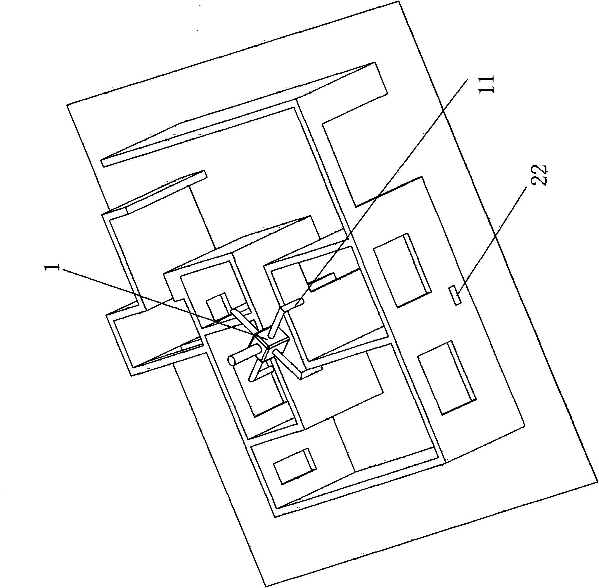
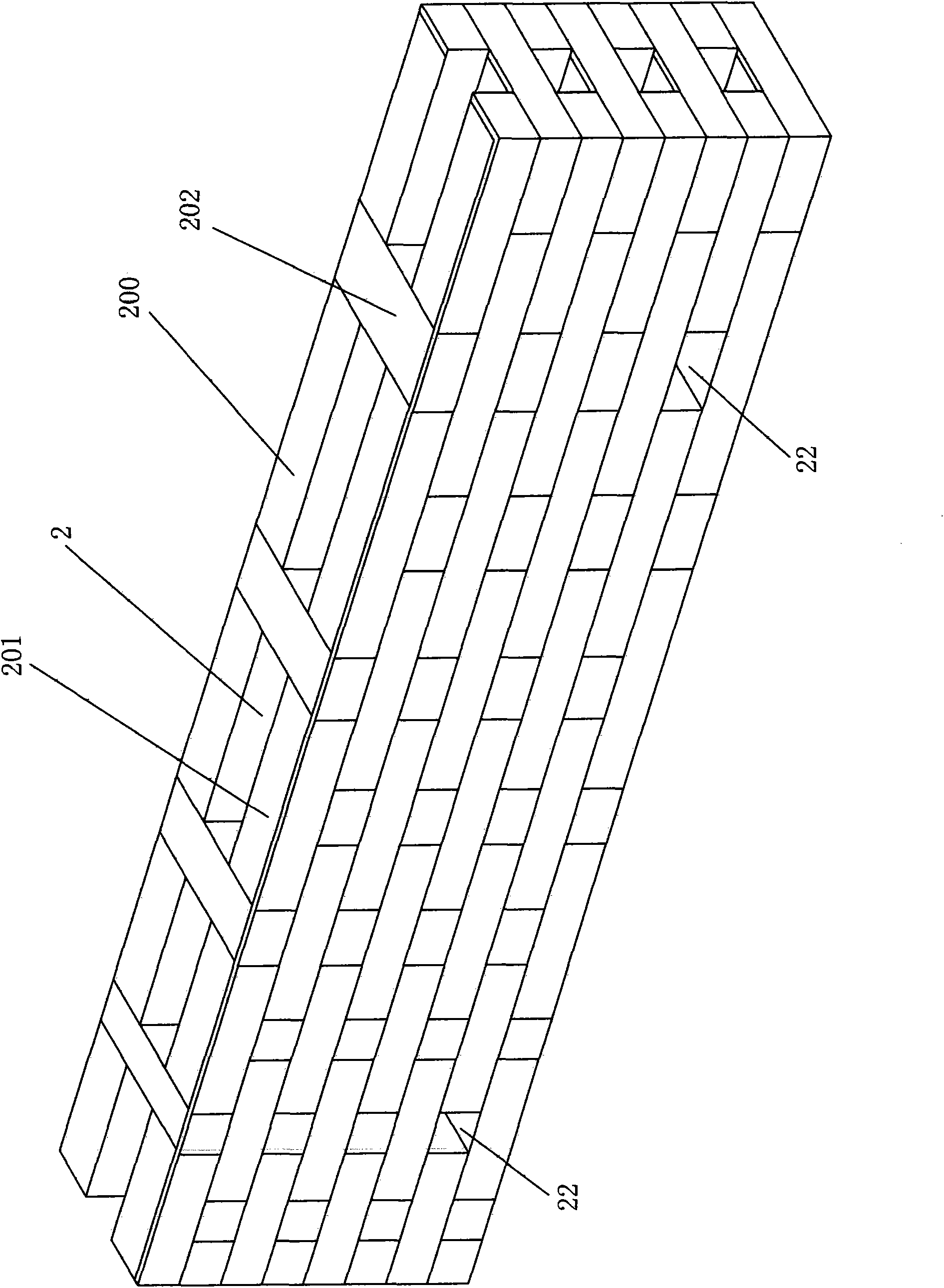
[0024] A building fresh air heat exchange system, the building includes a plurality of rooms, including rooms separated from the outside world, the fresh air heat exchange system includes an air supply device 1, and the air supply device 1 is a fan; the air outlet pipe of the air supply device 1 11 respectively communicate with the upper part of each room of the building; the outer wall of the room separated from the outside world of the building is provided with a heat exchange space interlayer 2, and one side of the heat exchange space interlayer 2 is connected to the interior of the room through the air outlet 21 The other side of the interlayer 2 in the heat exchange space communicates with the outside world through the air outlet 22; the air outlet 21 is arranged on the inner side of the outer wall, and the air outlet 22 is arranged on the outer side of the outer wall. The air outlet hole 21 and the air exhaust hole 22 are arranged at different heights on the outer wall. ...


PUM


Abstract

The invention discloses a new air heat-exchange system for a building which comprises a plurality of rooms. The new air heat-exchange system is characterized by comprising an air supply device, wherein the air outlet pipe of the air supply device is respectively communicated with the upper part of each room of the building; a heat-exchange space interlayer is arranged in an external wall of each room of the building; one side of the heat-exchange space interlayer is communicated with the inside of each room through an air outlet hole, and the other side of the heat-exchange space interlayer is communicated with the outside through an air discharge hole; and the air outlet hole and the air discharge hole are arranged at different heights in the external wall. Due to the air supply device arranged in each room of the building and a heat-exchange space arranged in the external wall, the air is supplied to the heat-exchange space to exchange heat with the hot air in the external wall and discharge the hot air outside from the air discharge hole. The new air heat-exchange system has simple structure, low cost, low energy consumption and low noise and completely accords with the requirements of national policies for saving energy and reducing emissions.

Description

【Technical field】 [0001] The invention relates to a building fresh air heat exchange system, in particular to a building fresh air heat exchange system capable of exchanging and renewing the air in the building and exchanging heat for the hot air in the building wall interlayer. 【Background technique】 [0002] Ventilation and heat exchange methods for existing buildings include: [0003] 1. Open windows for ventilation and heat exchange: But this most direct and primitive method of ventilation and exhaust is obviously not advisable and has many disadvantages. Open windows for ventilation and blind airflow. The chaotic airflow may bring the peculiar smell of the bathroom and kitchen into the living room and bedroom, and entrain a lot of dust. While affecting indoor cleanliness, noise pollution cannot be avoided. In addition, opening windows when using cold and heat source facilities will cause energy waste, which is obviously not advisable in this modern society that pays at...

Claims


Application Information

Patent Timeline
Patent Type & Authority Applications(China)
IPC IPC(8): F24F7/10E04B2/30
Inventor 钟粤
Owner 钟粤
Learn More