
Digital delay phase-locked loop

A delay phase-locked loop, digital technology, applied in the field of phase-locked loops, can solve the problems of limiting the application of digital phase-locked loops, increasing design complexity and manufacturing costs, and large digital phase-locked loop circuit area, etc., to achieve increased work The effect of the frequency range

Active Publication Date: 2013-05-29
SEMICON MFG INT (SHANGHAI) CORP
View PDF0 Cites 0 Cited by
  • Summary
  • Abstract
  • Description
  • Claims
  • Application Information

AI Technical Summary

Problems solved by technology

[0004] The defect of this digital phase-locked loop is that its operating frequency range depends on the length of the delay chain of the main module, so the digital phase-locked loop can only work in a certain frequency range, which greatly limits the application of digital phase-locked loops
[0005] In addition, the circuit area of ​​the digital phase-locked loop is proportional to the length of the delay chain, that is, the longer the delay chain is, the larger the circuit area is, and the additional compensation is required considering the deviation of the process, operating temperature, and power supply voltage. circuit, the overall circuit area of ​​the digital phase-locked loop will become larger, thereby increasing design complexity and manufacturing cost

Method used


Image

  • Digital delay phase-locked loop
  • Digital delay phase-locked loop
  • Digital delay phase-locked loop

Examples


Embodiment Construction

[0025] In order to make the technical features of the present invention more comprehensible, the present invention will be further described below in conjunction with the accompanying drawings and embodiments.

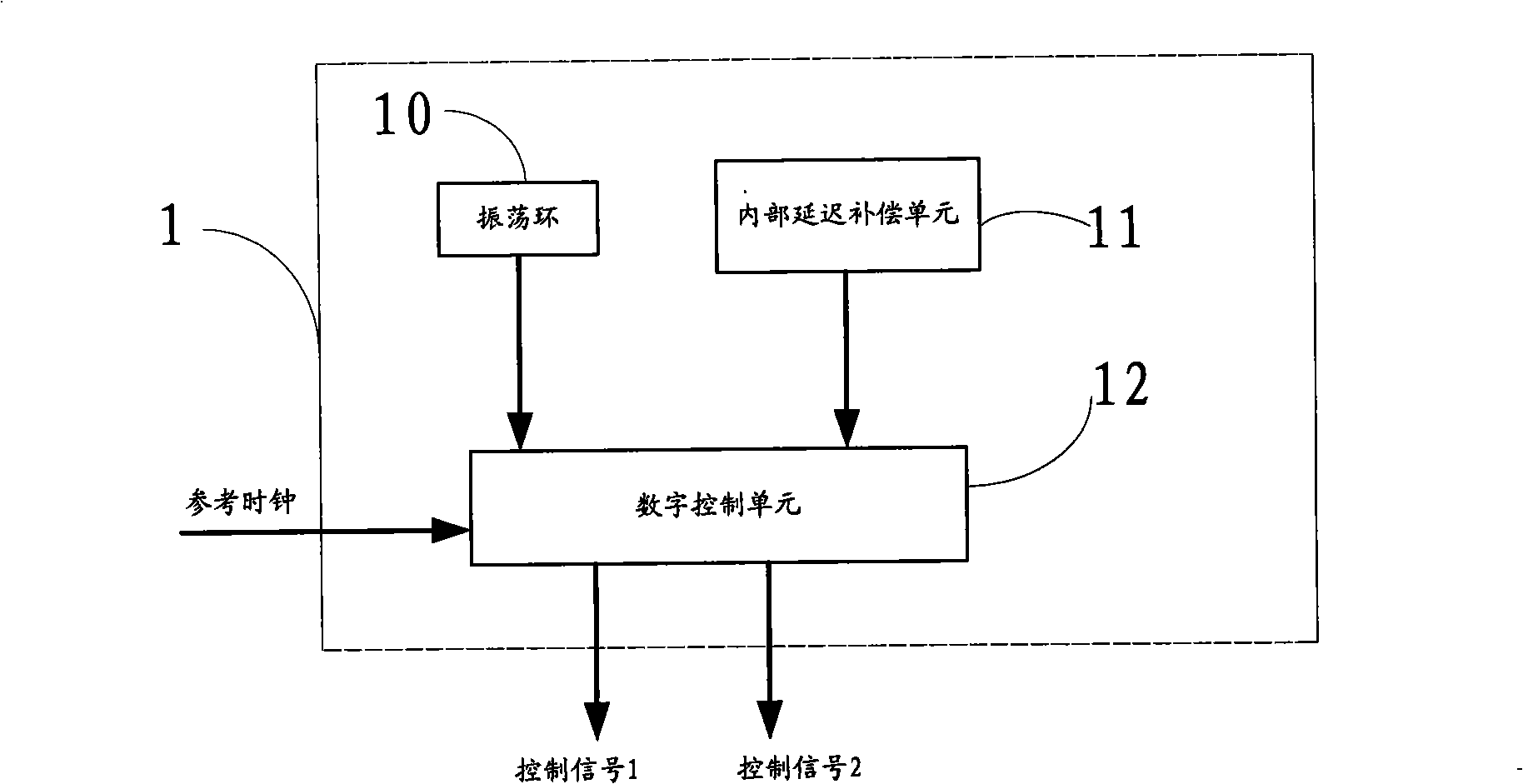
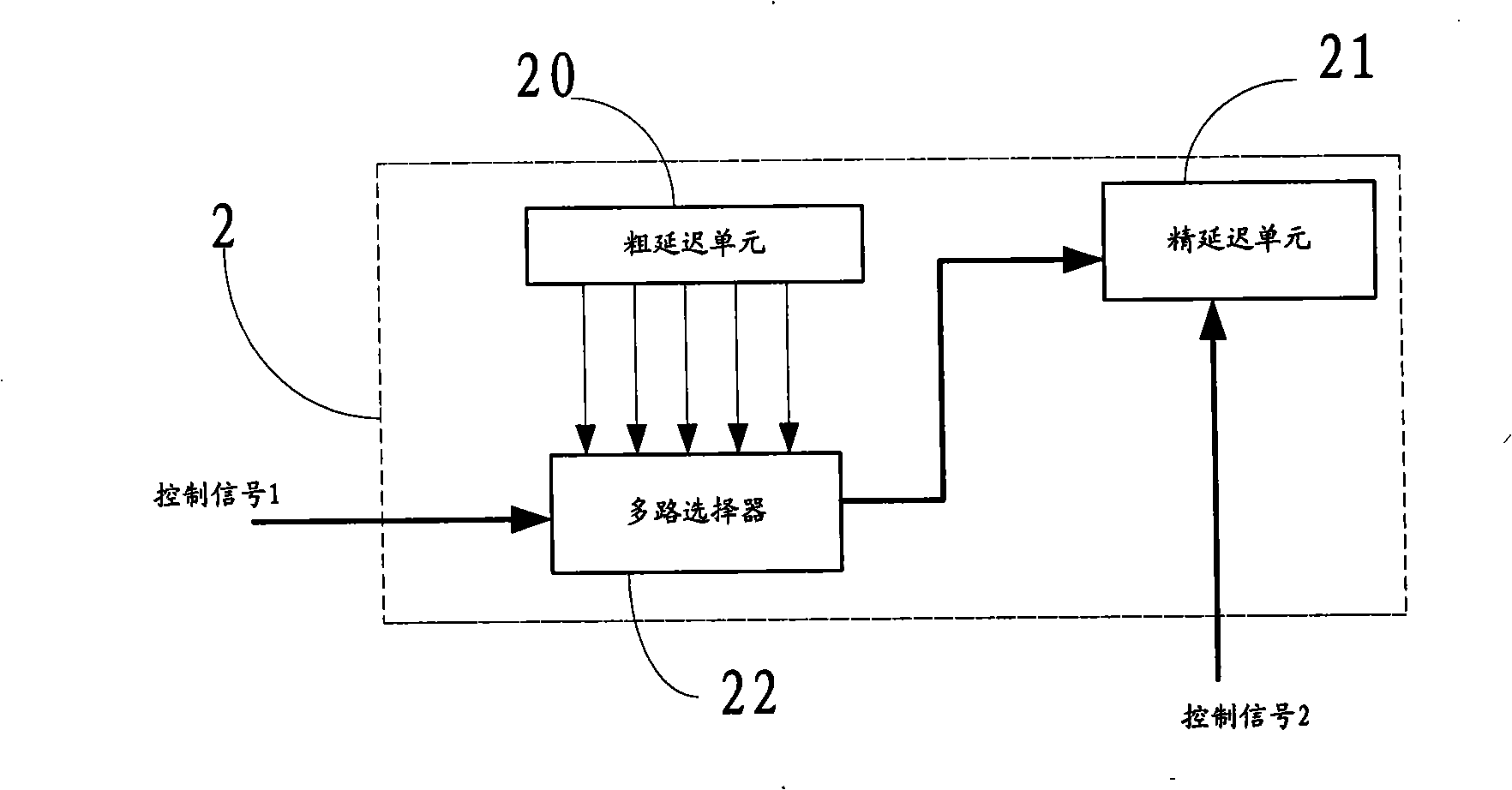
[0026] see figure 1 , figure 2 , figure 1 It is a schematic structural diagram of the main module 1 of the digital delay-locked loop in the embodiment of the present invention, figure 2 It is a schematic structural diagram of the slave module 2 of the digital delay-locked loop in the embodiment of the present invention. Wherein, the slave module 2 includes a coarse delay unit 20 , a fine delay unit 21 and a multiplexer 22 .

[0027] The master module 1 delays the reference clock to generate a series of delayed signals, and compensates the delayed signals according to the inherent delay of both the fine delay unit 21 and the multiplexer 22 in the slave module 2, thereby obtaining precise control Delay signal to slave module 2.

[0028] The main module 1 includes:...


PUM


Abstract

The invention provides a digital delay phase-locked loop which comprises a slave module and a main module. The slave module comprises a coarse delay unit, a precise delay unit and a multi-route selector; the main module comprises an oscillation ring, an internal delay compensating unit and a CNC unit, wherein the oscillation ring is used for generating oscillating clock signals; the internal delay compensating unit is used for compensating inherent delay of the precise delay unit in the slave module and delay time of the multi-route selector; and the CNC unit is used for generating an enabling signal in a plurality of reference clock periods, counting the oscillating clock signals generated by the oscillation ring and digitizing the reference clock periods according to a value acquired bycounting. The digital delay phase-locked loop digitizes the reference clock periods and increases one bit of the controller in the control unit by changing a counter in the digital control unit and counting and decoding an oscillation signal, so a working range can be doubled and a working frequency range of the digital delay phase-locked loop is enlarged.

Description

technical field [0001] The invention relates to a phase-locked loop, in particular to a digital delay-locked loop. Background technique [0002] A phase-locked loop is a feedback circuit whose function is to synchronize the phase of the clock on the circuit with an external clock. During the working process of the phase-locked loop, when the frequency of the output signal is equal to the frequency of the input signal, the output voltage and the input voltage maintain a fixed phase difference, that is, the phase of the output voltage and the input voltage is locked, which is phase-locked The origin of the name of the ring. In the data acquisition system, the phase-locked loop is a very useful synchronization technology. Through the phase-locked loop, different data acquisition boards can share the same sampling clock. It is widely used in broadcast communication, frequency synthesis, automatic control, Clock synchronization and pulse width adjustment and other technical fie...

Claims


Application Information

Patent Timeline
Patent Type & Authority Patents(China)
IPC IPC(8): H03L7/08
Inventor 郑佳鹏鲁雪晴李伟王阳元
Owner SEMICON MFG INT (SHANGHAI) CORP
Learn More