Knitting needle bed swinging mechanism of high-speed tricot machine

A high-speed warp knitting machine and warp knitting machine technology, which is applied in the directions of warp knitting, knitting, textiles and papermaking, can solve the problems of difficult processing and manufacturing of cam mechanisms, unsuitable high speed of cam mechanisms, and limiting the speed of warp knitting machines. Easy to manufacture, wide range of travel speed ratio coefficients, easy to adjust

Active Publication Date: 2011-08-17
临沂高新区金蓝领劳务有限公司
View PDF7 Cites 0 Cited by
  • Summary
  • Abstract
  • Description
  • Claims
  • Application Information

AI Technical Summary

Problems solved by technology

The transmission requirement of the travel speed ratio coefficient is about 2, which is relatively large. In order to realize the movement requirement, the knitting needle swing mechanism used on the warp knitting machine generally adopts a cam mechanism. Since the cam mechanism is not suitable for high speed, the speed of the warp knitting machine is limited. Further improvement, and the cam mechanism is difficult to manufacture and the cost is high

Method used


Image

  • Knitting needle bed swinging mechanism of high-speed tricot machine
  • Knitting needle bed swinging mechanism of high-speed tricot machine
  • Knitting needle bed swinging mechanism of high-speed tricot machine

Examples


Embodiment Construction

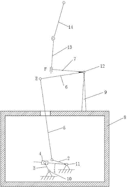
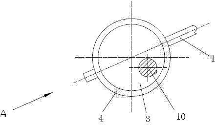
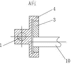
[0018] In the embodiment shown in the accompanying drawings, the oil tank 8 of the warp knitting machine is provided with a main shaft 10 and a bearing pin 11 which are respectively supported by a support frame and are parallel to each other, and the oil tank 8 of the warp knitting machine is provided with a pendulum shaft 12 supported by a bracket 9 and a weaving pin. The needle bed 14 and the needle bed seat 13 supporting the needle bed 14. The main shaft 10, pin shaft 11 and swing shaft 12 are all long axes equal to the width of the machine. The main shaft 10 is the main movement power input shaft of the warp knitting machine, driven by a motor. The needle bed active swing arm 6 and the needle bed driven swing arm 7 are fixed on the swing shaft 12 , and the needle bed active swing arm 6 and the needle bed driven swing arm 7 swing as a whole with the rotation of the swing shaft 12 . The needle bed seat 13 is inserted in the guide cylinder 7-1 of the driven swing arm 7 of th...


PUM


Abstract

The invention relates to a knitting needle bed swinging mechanism of a high-speed tricot machine, provided with a main shaft, a swinging shaft, a knitting needle bed and a needle bed seat for supporting the knitting needle bed. A needle bed driving swinging arm and a needle bed driven swinging arm are fixed on the swinging shaft, a knitting seat and the needle bed driven swinging arm are connected in a moving pair mode, an eccentric wheel is fixed on the main shaft and connected with a guiding sleeve in a revolute pair mode, a pin shaft is arranged at one side of the main shaft in parallel and fixedly provided with a guiding rod and a connecting rod, the guiding sleeve is provided with a guiding rod hole, the guiding rod passes through the guiding rod hole in the guiding sleeve and forms a moving pair together with the guiding sleeve, and the connecting rod is connected with the guiding rod in a revolute pair mode penetrates through an oil tank and connected with the needle bed drivenswinging arm in a revolute pair mode. The invention is suitable for being applied to the high-speed tricot machine, the moving pair in the whole mechanism is a plane low pair instead of a high pair so that the processing and the manufacture are simple and convenient, and the manufacture cost is decreased. The invention can realize a wide range of travel velocity ratios and is more suitable for different use requirements.

Description

technical field [0001] The invention relates to a warp knitting machine component, in particular to an oscillating motion mechanism of a warp knitting machine needle bed. Background technique [0002] In the process of weaving fabric by warp knitting machine, it is one of the important processes to form the fabric structure by taking the yarn from the hook of the knitting needle. In order to form the loop correctly, it is generally required to have the movement of the knitting needle, the movement of the bar and the settlement movement to cooperate with each other. . The movement of the bar is generally a swing around a fixed point. When the number of bars is small, its mass and moment of inertia are small, and the inertial force and moment of inertia generated during the swing have little influence on the speed of the machine. For a long time, its mass and moment of inertia are large. If it still swings, there will be a large inertial force and moment of inertia, which is ...

Claims


Application Information

Patent Timeline
Patent Type & Authority Patents(China)
IPC IPC(8): D04B27/08
Inventor 曹清林
Owner 临沂高新区金蓝领劳务有限公司
Why Eureka
Try Eureka