Oil supplying device

An oil supply device, valve device technology, applied in liquid cooling, engine components, machines/engines, etc., can solve problems such as aging, increased emissions, splash loss, etc., to prevent oil aging, reduce emissions, and reduce splash loss. Effect

Inactive Publication Date: 2013-06-12
DR ING H C F PORSCHE AG
View PDF3 Cites 0 Cited by
  • Summary
  • Abstract
  • Description
  • Claims
  • Application Information

AI Technical Summary

Problems solved by technology

However, the quantity of lubricating oil that has been supplied hitherto for piston cooling or lubrication often considerably exceeds the quantity required for cylinder running surface lubrication alone, with consequences for oil foaming, splash losses, oil aging and, if excess oil Disadvantages of increased emissions through these piston rings into the combustion chamber and combustion there

Method used


Image

  • Oil supplying device
  • Oil supplying device
  • Oil supplying device

Examples


Embodiment Construction

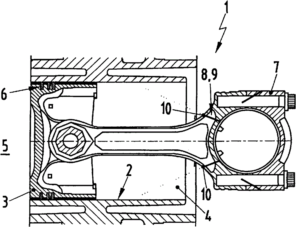
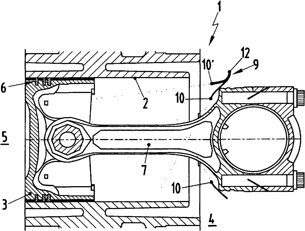
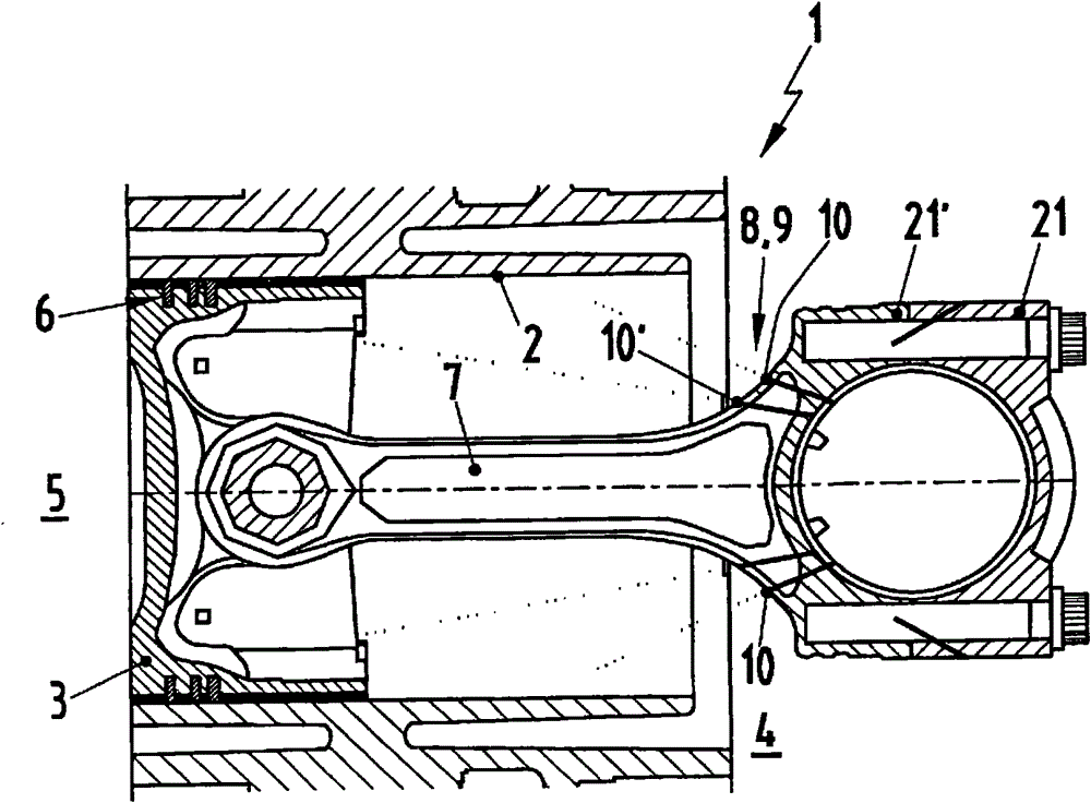
[0029] according to Figure 1 to Figure 3 , a piston-cylinder assembly 1 has in each case a piston 3 which can reciprocate in a cylinder 2 in a translational manner. Piston-cylinder assembly 1 can be embodied here as an internal combustion engine, in particular in a motor vehicle. In order to seal a crankcase interior 4 from a combustion chamber 5, so-called piston rings 6 are conventionally arranged on the piston 3, which are inserted into an outwardly open annular recess on the piston skirt. Groove and extended slide in cylinder 2. as from figure 1 It can also be seen that a connecting rod 7 has an oil supply device 9 arranged therein (see Figure 4 and Figure 5 ), the oil supply device has at least one oil nozzle 10, which is directed to the cylinder 2 and is used to lubricate the cylinder working surface. Another oil nozzle 10' can for example be directed towards the piston 3 (see figure 2 and image 3 ) and oil is sprayed onto said piston 3 at least temporarily i...


PUM


Abstract

The oil supplying device (9) has a nozzle device (8) with an oil inlet and an oil nozzle (10). The nozzle device is aligned on a cylinder (2) and on a piston (3). The oil supplying device is formed, such that the lubricating of the cylinder takes place constantly during the cooling of the piston is connected or the lubricating of the cylinder already takes place at a low oil pressure, in which no cooling of the piston takes place.

Description

technical field [0001] The invention relates to an oil supply device for lubricating a cylinder and / or cooling a piston. The invention also relates to an internal combustion engine equipped with an oil supply device of the type described. Background technique [0002] DE 10 2005 006 808 A1 discloses a generic oil supply device for lubricating and / or cooling pistons and cylinders in different engine operating states. Here, the oil supply device comprises a substantially tubular oil supply distributor having an inlet connected to a source of pressurized engine oil and having at least one outlet connected to at least one on the fuel rail. The oil supply rail comprises a longitudinal distribution pipe with integral nozzles of an oil injection device and fastening seats. Known oil supply rails are intended to enable improved engine operation. [0003] DE 102 61 180 A1 discloses a temperature-controlled oil injection nozzle for piston cooling, which comprises a regulating valv...

Claims


Application Information

Patent Timeline
Patent Type & Authority Patents(China)
IPC IPC(8): F01M1/08F01P3/08
CPCF01M1/08F01P3/08
Inventor F·迈尔J-G·乌尔里希
Owner DR ING H C F PORSCHE AG
Why Eureka
Try Eureka