Concrete pump truck and concrete delivery pump exchange system

A concrete delivery pump and reversing system technology, applied in pump control, building material processing, construction, etc., can solve problems such as unsatisfactory buffering effect, achieve the effect of reducing shock and vibration and improving stability

Inactive Publication Date: 2010-08-04
XCMG CONSTR MACHINERY
View PDF0 Cites 20 Cited by
  • Summary
  • Abstract
  • Description
  • Claims
  • Application Information

AI Technical Summary

Problems solved by technology

Therefore, the buffering effect achieved by optimizing the transition neutral position of the main directi

Method used


Image

  • Concrete pump truck and concrete delivery pump exchange system
  • Concrete pump truck and concrete delivery pump exchange system
  • Concrete pump truck and concrete delivery pump exchange system

Examples


Embodiment Construction

[0024] The core of the present invention is to provide a concrete delivery pump reversing system, the shock and vibration caused by the reversing of the hydraulic oil in the pumping main cylinder are relatively small. Another core of the present invention is to provide a concrete pump truck including the reversing system of the above-mentioned concrete delivery pump.

[0025] In order to enable those skilled in the art to better understand the solution of the present invention, the present invention will be further described in detail below in conjunction with the accompanying drawings and specific embodiments.

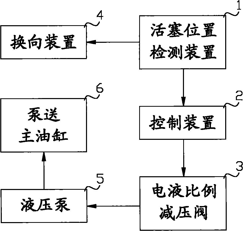
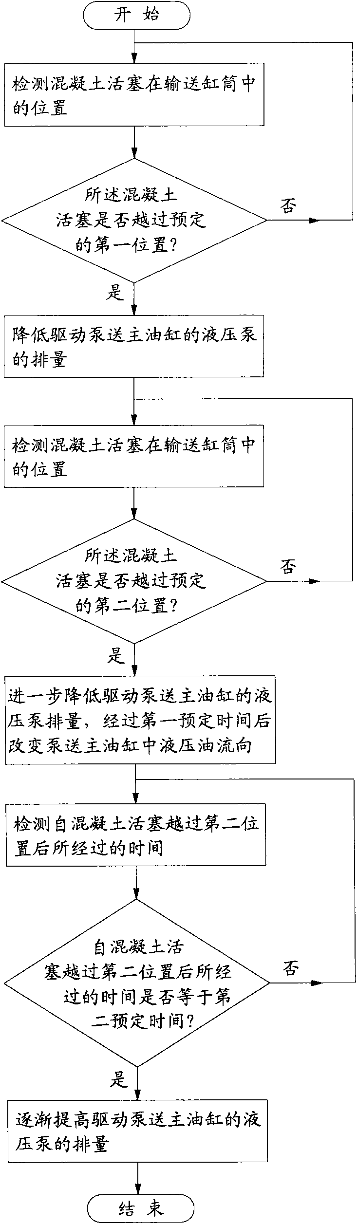
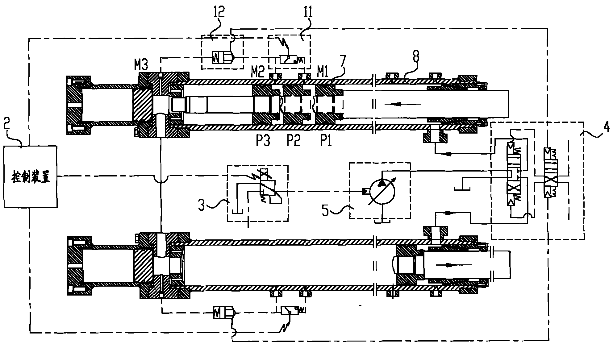
[0026] Please refer to Figure 1 to Figure 3 , figure 1 It is a schematic structural diagram of the concrete delivery pump reversing system provided by a specific embodiment of the present invention; figure 2 It is a working flow chart of the concrete delivery pump reversing system provided by a specific embodiment of the present invention; image 3 It is a schema...


PUM


Abstract

The invention discloses a concrete delivery pump exchange system. After a concrete piston passes over the first position near the stroke end of the piston, the delivery capacity of the hydraulic pump of a pumping main cylinder is reduced so as to realize the pre-deceleration of the concrete piston; after the concrete piston passes over the second position further near the stroke end of the piston, the delivery capacity of the hydraulic pump can be reduced once again, so that the delivery capacity of the hydraulic pump remains a lower level; and then, when the delivery capacity of the hydraulic pump is lower, even close to zero drainage, the flow direction of the hydraulic oil in the pumping main cylinder is changed via an exchange device, thus the impact and the vibration caused by the direction change of the hydraulic oil in the pumping main cylinder are effectively reduced, and the stability of the concrete pump car in the working process can be greatly enhanced.

Description

technical field [0001] The invention relates to the technical field of engineering machinery, in particular to a concrete pump truck. The invention also relates to a concrete delivery pump reversing system for a concrete pump truck. Background technique [0002] At present, concrete pump trucks are widely used in construction sites. When pumping concrete, the concrete pump truck pushes the concrete pistons in the two delivery cylinders to reciprocate through two pumping master cylinders. The concrete piston retracts under the driving of the pumping main cylinder, thereby sucking concrete into the delivery cylinder; at the same time, the concrete piston in the other delivery cylinder is extended under the driving of the pumping main cylinder, so that it can be pumped in the previous stroke The pre-absorbed concrete is pushed out, thus completing the pumping. In order to ensure the continuity of pumping, two main pumping cylinders respectively drive a concrete piston to rec...

Claims


Application Information

Patent Timeline
IPC IPC(8): F04B49/00E04G21/04
Inventor 史先信徐怀玉沈千里马传杰
Owner XCMG CONSTR MACHINERY
Why Eureka
Try Eureka