Chip image collecting and locating device based on rotary reflector
An image acquisition and positioning device technology, applied in the direction of using optical devices, measuring devices, installation, etc., can solve the problems of automatic focusing, low efficiency of chip placement, image distortion, etc., and achieves improved chip placement efficiency and continuous chips. Mounting work, the effect of simple structure
- Summary
- Abstract
- Description
- Claims
- Application Information
AI Technical Summary
Problems solved by technology
Method used
Image
Examples
specific Embodiment approach 1
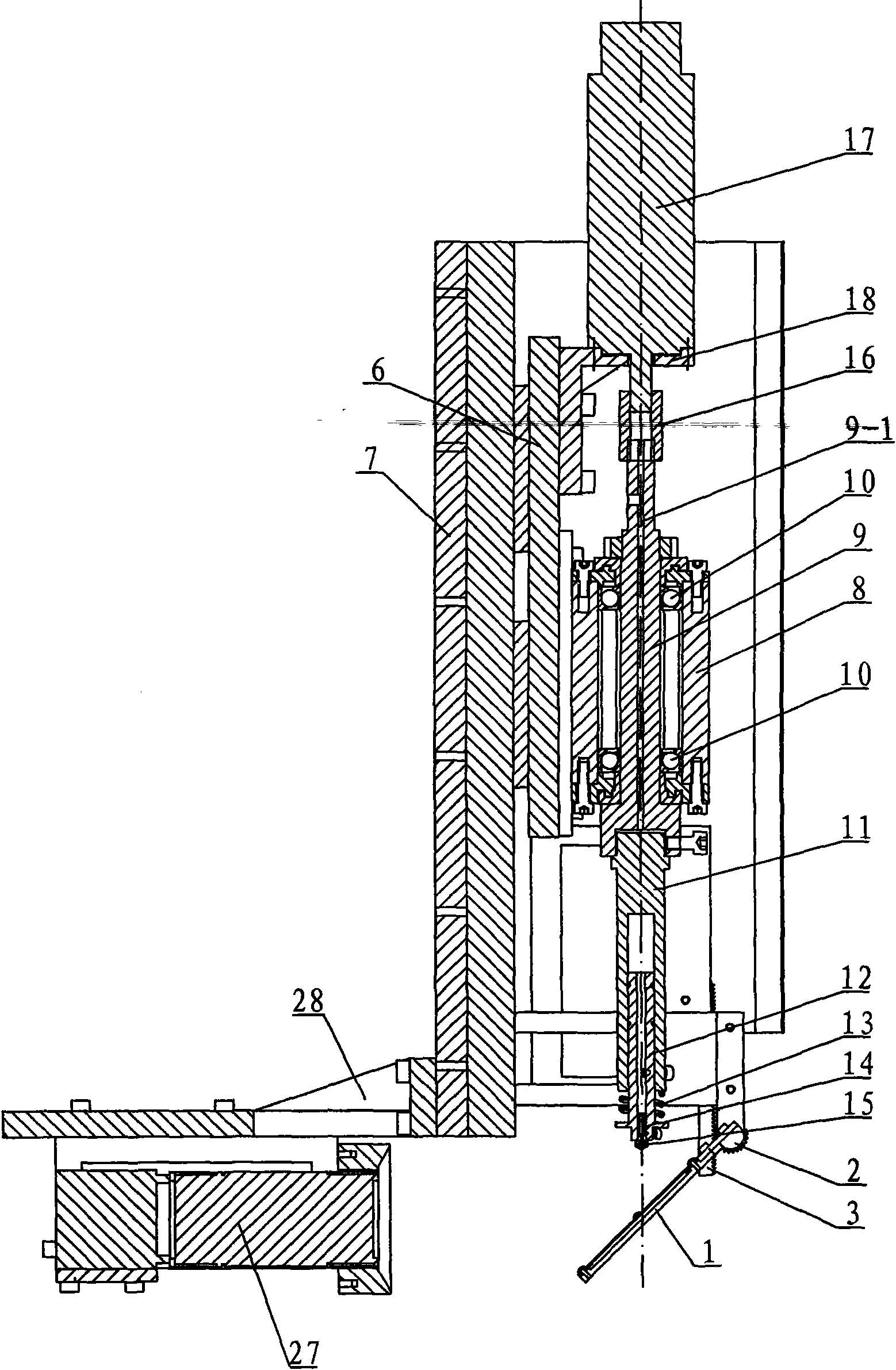
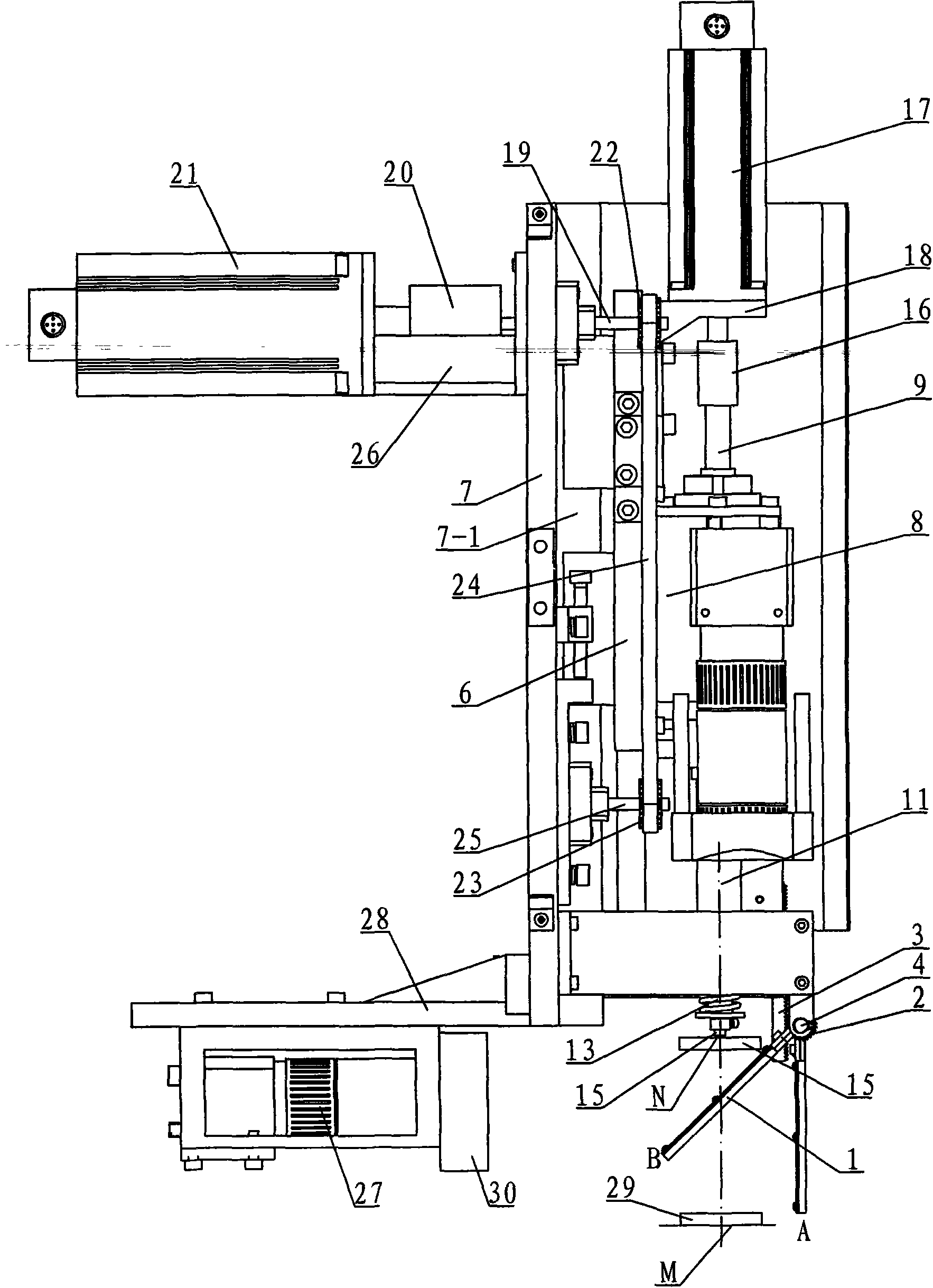
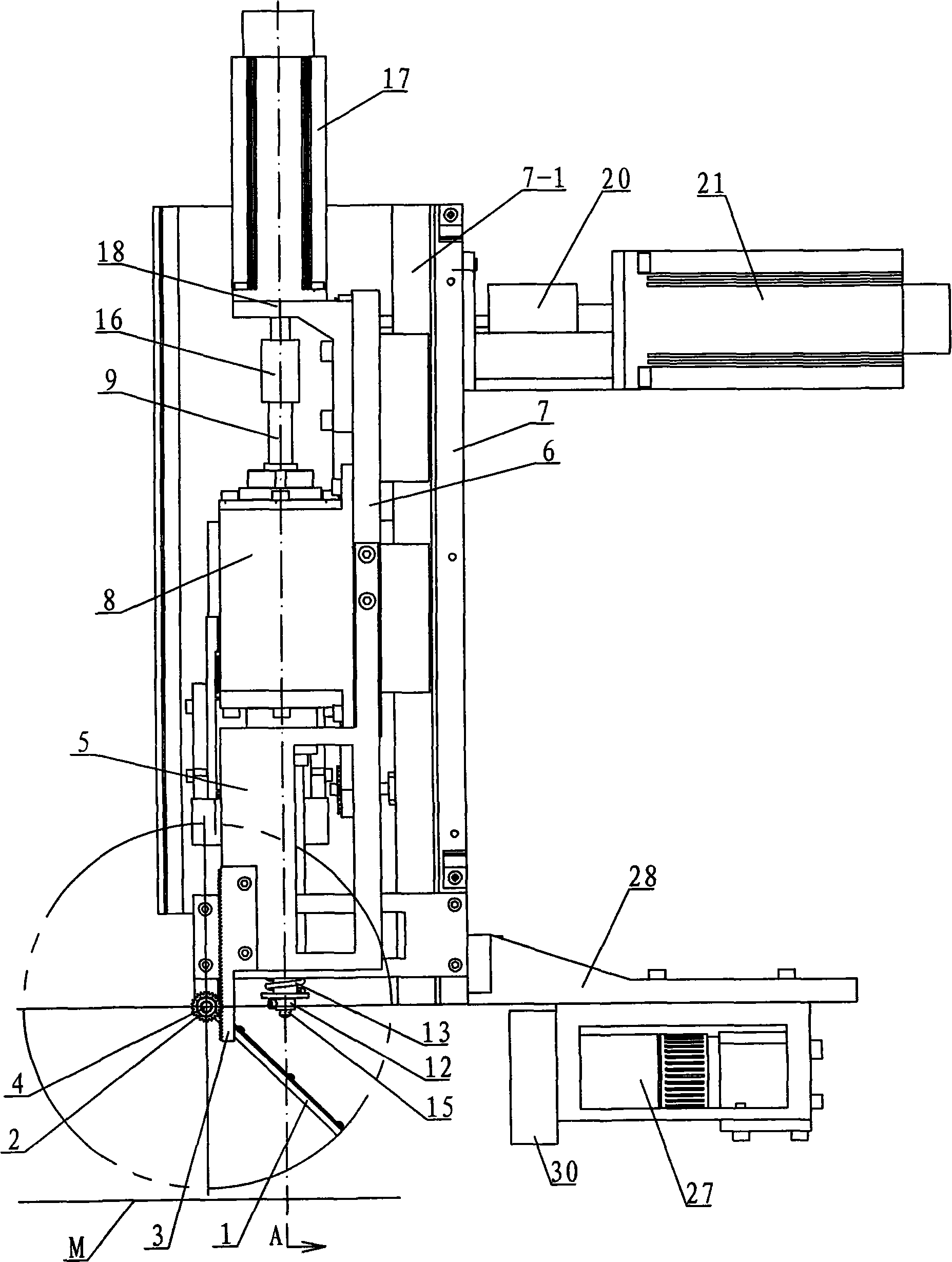
[0008] Specific implementation mode one: combine Figure 1 ~ Figure 3 Describe this embodiment, this embodiment includes a reflector assembly 1, a gear 2, a rack 3, a rotating shaft 4, a support plate 5, a moving base 6, a frame 7, a nozzle sleeve 8, a transmission shaft 9, and two ball bearings 10. Suction nozzle shaft 11, suction nozzle sleeve rod 12, spring 13, suction nozzle rod 14, suction nozzle 15, first coupling 16, rotating motor 17, rotating motor seat 18, upper synchronous belt shaft 19, second coupling Shaft device 20, moving motor 21, upper synchronous belt pulley 22, lower synchronous belt pulley 23, synchronous belt 24, lower synchronous belt shaft 25, motor support 26, camera 27, camera support 28 and light source 30, establish on frame 7 There are guide rails 7-1, the mobile base 6 is installed on the frame 7, the mobile base 6 moves up and down along the frame 7, the suction nozzle sleeve 8 is fixedly connected with the mobile base 6, and the transmission sha...
specific Embodiment approach 2
[0009] Specific implementation mode two: combination Figure 4 Describe this embodiment, the reflector assembly 1 of this embodiment is made up of reflector base plate 1-1 and reflector 1-2, the upper end surface of reflector base plate 1-1 is provided with reflector groove 1-1-1, reflector 1-2 is contained in the reflector groove 1-1-1. Other components and connections are the same as those in the first embodiment.
specific Embodiment approach 3
[0010] Specific implementation mode three: combination Figure 5 The present embodiment will be described. The gear 2 of the present embodiment is a sector gear, and the angle α between the two side faces of the sector gear is 60-70°. This design makes the mirror assembly 1 rotate within the range of 0-45° with the vertical plane, so that the camera 27 can acquire the moving image of the chip when the mirror assembly 1 is at 45° with the vertical plane. Other compositions and connections are the same as those in Embodiment 1 or 2.
[0011] How it works: When die attaching, see figure 2 , the chip 29 is placed in the M position, at this moment, the reflector assembly 1 is parallel to the rack 3 (the position of the reflector assembly 1 is located as figure 2 point A), start the mobile motor 21, the upper synchronous belt shaft 19 drives the upper synchronous belt pulley 22 to rotate, the synchronous belt 24 rotates accordingly, the suction nozzle sleeve 8 and the mobile bas...
PUM
 Abstract
Description
Claims
Application Information
 - R&D
- Intellectual Property
- Life Sciences
- Materials
- Tech Scout
- Unparalleled Data Quality
- Higher Quality Content
- 60% Fewer Hallucinations
Browse by: Latest US Patents, China's latest patents, Technical Efficacy Thesaurus, Application Domain, Technology Topic, Popular Technical Reports.
© 2025 PatSnap. All rights reserved.Legal|Privacy policy|Modern Slavery Act Transparency Statement|Sitemap|About US| Contact US: help@patsnap.com


