
Quick detection and protection device for electric potential of direct-current traction power supply return current rail

A protection device and DC traction technology, applied in emergency protection circuit devices, emergency protection devices with automatic disconnection, circuit devices, etc., can solve the problem that the accuracy of protection action response speed cannot fully meet the requirements of use, and improve the protection response Speed, guaranteed endurance, and improved operational reliability

Inactive Publication Date: 2010-08-04
ZHENJIANG DAQO SECHERON TRACTION POWER
View PDF2 Cites 5 Cited by
  • Summary
  • Abstract
  • Description
  • Claims
  • Application Information

AI Technical Summary

Problems solved by technology

The existing return rail potential limiting device cannot fully meet the requirements in terms of the accuracy of voltage monitoring and the response speed of protection actions.

Method used


Image

  • Quick detection and protection device for electric potential of direct-current traction power supply return current rail
  • Quick detection and protection device for electric potential of direct-current traction power supply return current rail
  • Quick detection and protection device for electric potential of direct-current traction power supply return current rail

Examples


Embodiment Construction

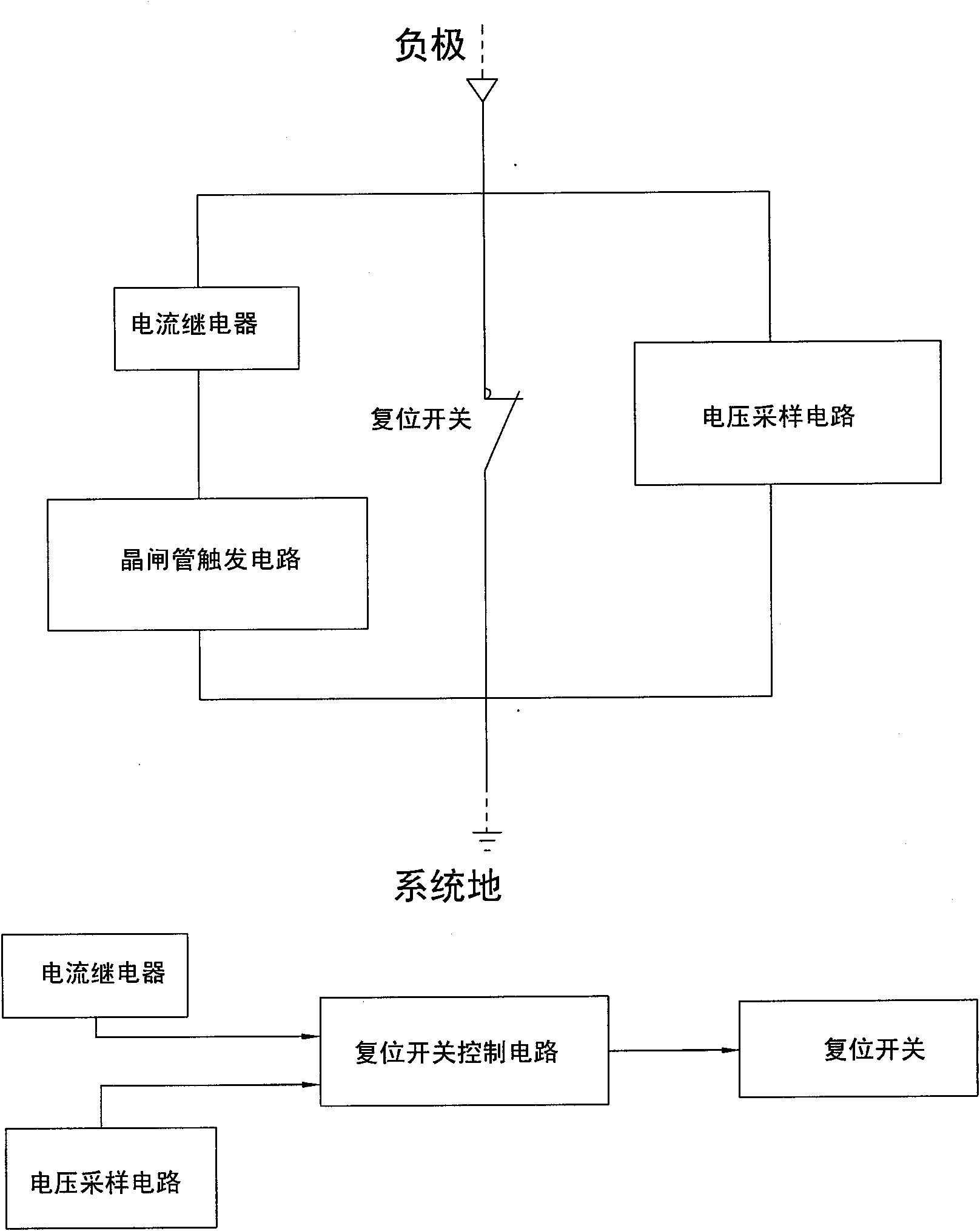
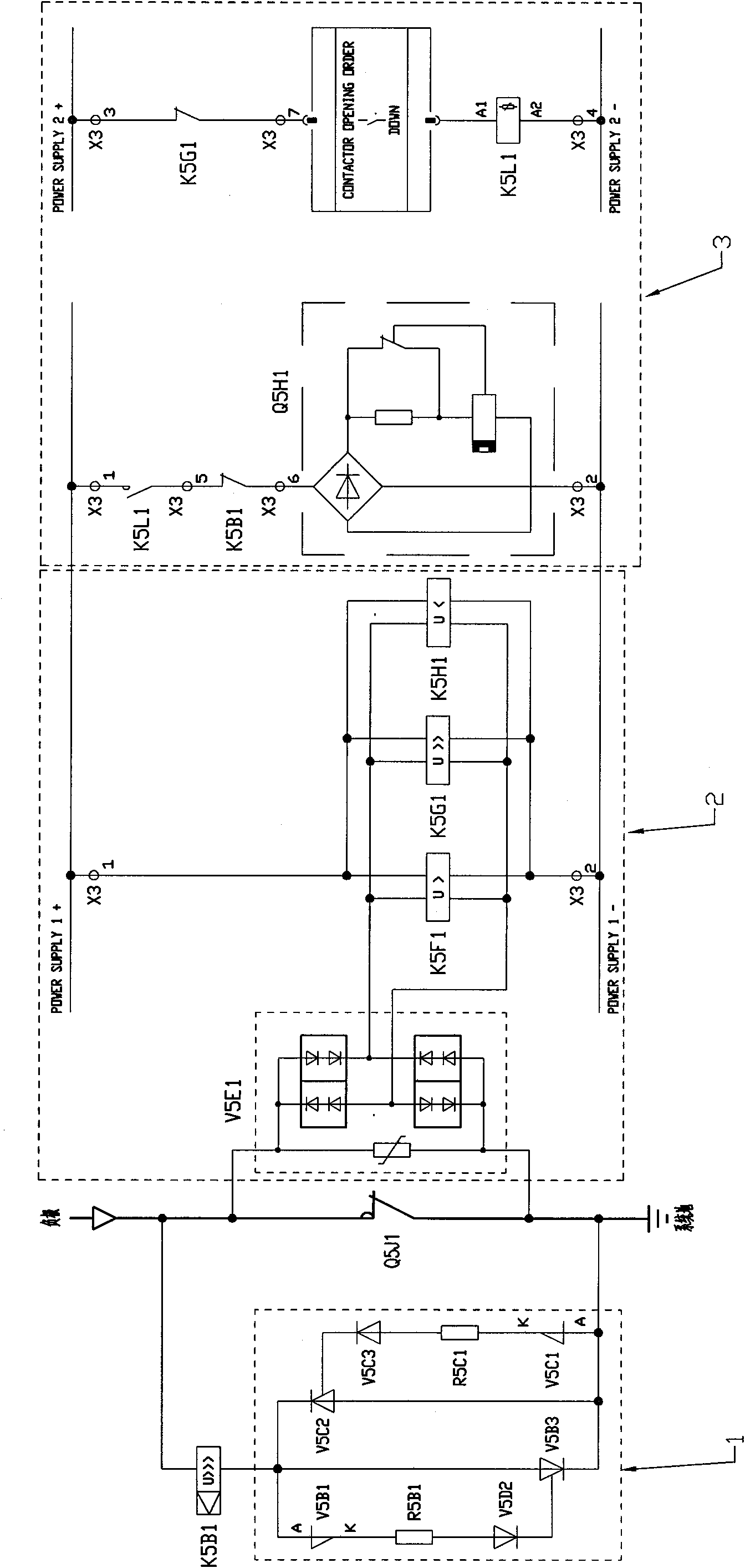
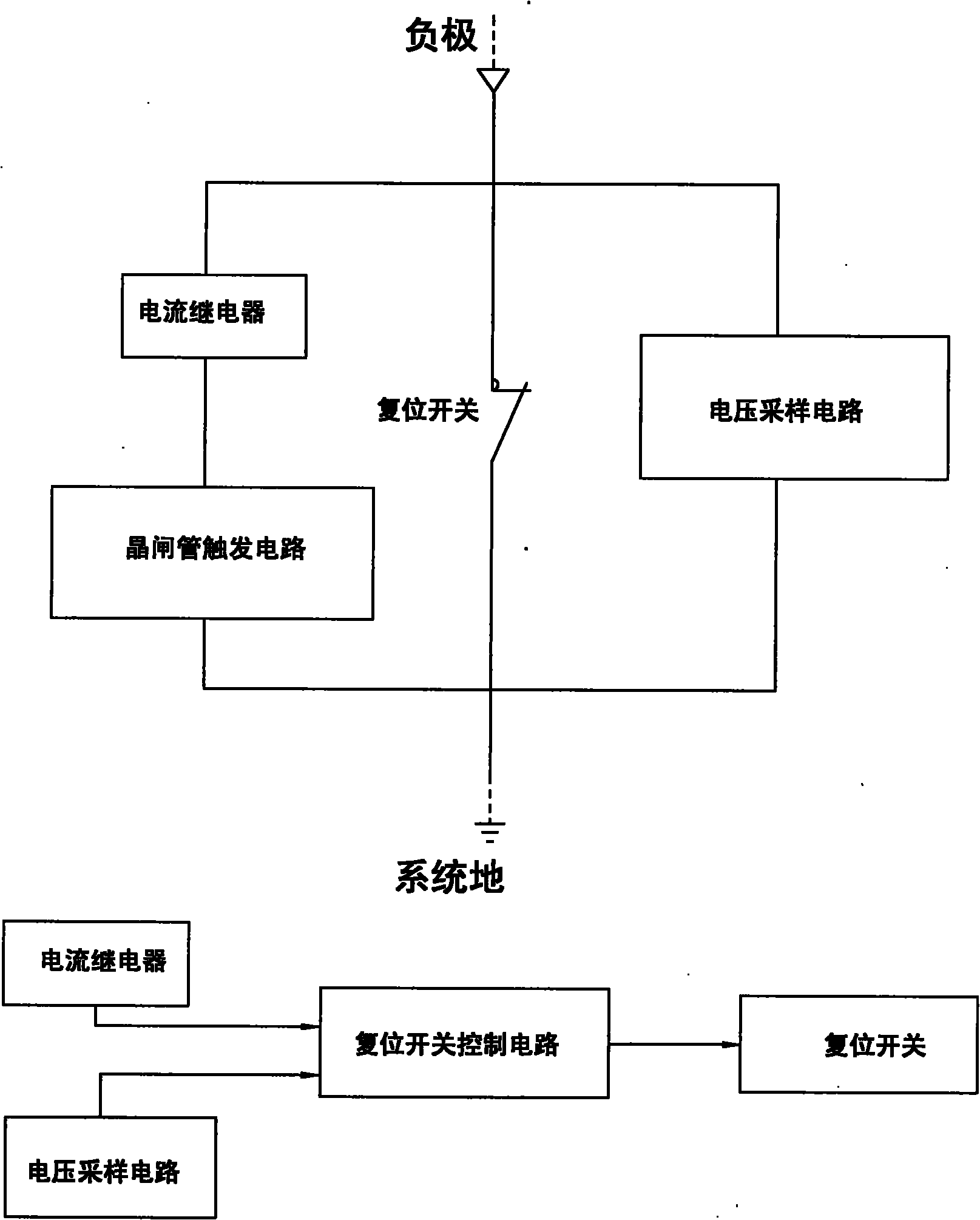
[0008] Such as figure 1 , figure 2 As shown, the embodiment of the device includes a reset switch Q5J1 connected between the negative return rail and the earth, a set of thyristor trigger circuit 1 and the current relay K5B1 connected in parallel with the reset switch between the negative return rail and the earth in series There is also a voltage sampling circuit 2 connected between the negative return rail and the ground; the output signals of the current relay and the voltage sampling circuit are output to the reset switch control circuit 3 to control the reset switch.

[0009] figure 2 In the shown embodiment, the potential difference between the track and the protection ground is applied to the voltage relays K5F1, K5G1, and K5H1 (constituting the voltage sampling circuit 2) after passing through the double rectification diode module V5E1.

[0010] When the potential difference reaches U > action setting value, K5F1 acts, and after a period of time delay, the reset sw...


PUM


Abstract

The invention relates to a monitoring device of a direct-current traction power supply system of urban rail traffic facilities, in particular to a quick detection and protection device for the electric potential of a direct-current traction power supply return current rail. The device comprises a reset switch, a group of thyristor trigger circuits and a current relay, wherein the reset switch is connected between a cathodal return current rail and the earth, the thyristor trigger circuits are sequentially connected in series, the current relay is connected with the reset switch in parallel between the cathodal return current rail and the earth, and a voltage sampling circuit is also connected between the cathodal return current rail and the earth; and the output signals of the current relay and the voltage sampling circuit are output to a control circuit of the reset switch. By the synergic monitoring of the current relay and the voltage sampling circuit, the invention can relevantly control different electric potential grades between the return current rail and the earth, can enhance the protection response speed under the condition of a potential difference, also ensures a certain tolerance capability of the return current rail to short-circuit current and enhances the operational reliability of the device.

Description

technical field [0001] The invention relates to a monitoring device for a DC traction power supply system of an urban rail transit facility, in particular to a rapid detection and protection device for a return rail potential of a DC traction power supply. Background technique [0002] In the DC traction power supply system of urban rail transit facilities, due to the existence of operating current and short-circuit current, it may cause a contact voltage between the return circuit (return rail) and the earth that exceeds the personal safety permit. It is necessary to use the return rail potential limiting device to limit the generation of overvoltage between the return circuit (return rail) and the earth. The existing return rail potential limiting devices cannot fully meet the requirements of use in terms of the accuracy of voltage monitoring and the response speed of protection actions. Contents of the invention [0003] The technical problem to be solved by the presen...

Claims


Application Information

Patent Timeline
IPC IPC(8): H02H3/26H02H3/07
Inventor 朱祥连朱忠建阚劲松
Owner ZHENJIANG DAQO SECHERON TRACTION POWER
Learn More