Electromagnetic heating device of iron finishing roller of iron finishing machine

A technology of electromagnetic heating device and ironing roller, which is applied in the direction of induction heating device, induction heating, textile and paper making, etc., which can solve the problems of difficult maintenance, slow heating speed, and low service life, and achieve the purpose of improving heat utilization rate and heating The effect of fast speed and high thermal efficiency

Inactive Publication Date: 2010-08-04
JIANGSU JUNFENG TEXTILE MACHINERY
View PDF4 Cites 17 Cited by
  • Summary
  • Abstract
  • Description
  • Claims
  • Application Information

AI Technical Summary

Problems solved by technology

However, it is not easy to introduce power into the rotating ironing roller, generate heat through the heating element, and overcome the influence of centrifugal force on the heating element
Conduction and heating devices with complex structures are placed in a closed high-temperature environment for a long time, with low service life, high failure rate, and difficult maintenance
In addition, in the electric heating device inside the ironing roller, the heat insulation effect of the insulating material and the heat dissipation performance of the roller body are often beyond people's expectations, so that the actual heating effect is not ideal. The main manifestations are: long preheating time, high temperature Slow speed, high heat loss

Method used


Image

  • Electromagnetic heating device of iron finishing roller of iron finishing machine
  • Electromagnetic heating device of iron finishing roller of iron finishing machine
  • Electromagnetic heating device of iron finishing roller of iron finishing machine

Examples


Embodiment Construction

[0019] Embodiments of the present invention are described in further detail below in conjunction with the accompanying drawings:

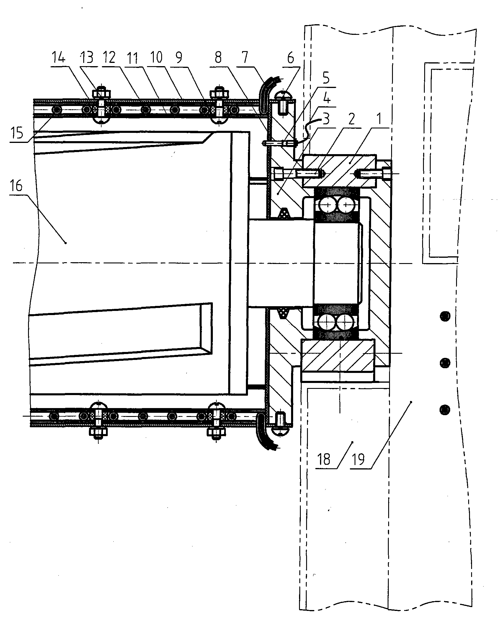
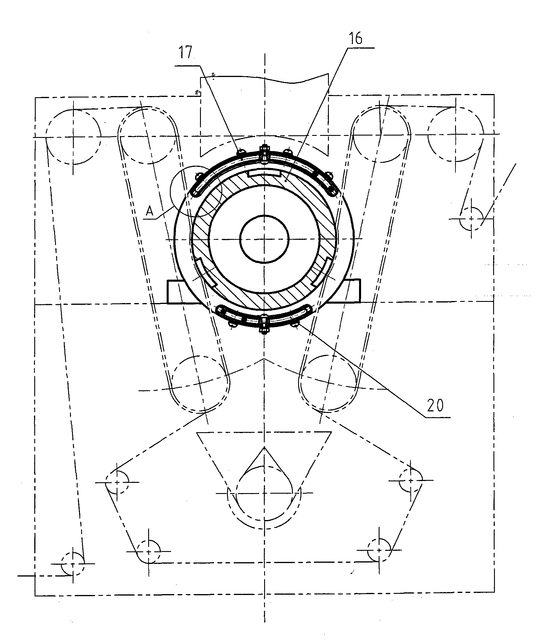
[0020] The ironing roller 16 is installed between the left and right racks 18 by two bearing seats 1. The outer side of the rack 18 is provided with an electric control box 19 containing electrical components such as an electromagnetic heating controller, a digital display screen and a power adjustment switch.

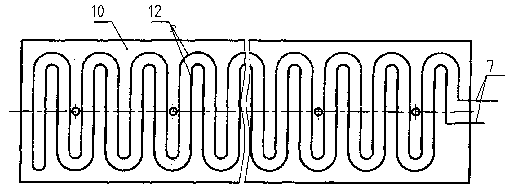
[0021] The present invention mainly includes an upper heating mantle assembly 17 and a lower heating mantle assembly 20. The upper and lower heating mantle assemblies 17 and 20 are arc-shaped, symmetrically arranged on the upper and lower sides of the ironing roller 16, and fixed to the two ends by screws 6. end cap 3. The end caps 3 are arranged on the inner side of the bearing seats 1 at both ends of the ironing roller 16 , and are fixed on the bearing seats 1 by screws 2 .

[0022] The upper and lower heating cover assemblies 17 and 20 ...


PUM


Abstract

The invention relates to an electromagnetic heating device of an iron finishing roller of an iron finishing machine. The electromagnetic heating device comprises an upper heating cover assembly (17) and a lower heating cover assembly (20), wherein the upper heating cover assembly and the lower heating cover assembly are in the shape of a circular arc and are symmetrically arranged at the outer side of an iron finishing roller (16); the upper heating cover assembly and the lower heating cover assembly consist of a cover casing (9), an inner clapboard (10), heating coils (12) and an outer clapboard (11); the heating coils (12) are arranged between the inner clapboard and the outer clapboard in a sinusoidal waveform curve; the heating coils can be externally connected with an electromagnetic induction heating controller in an electric cabinet; and an end cover is provided with a sensor for measuring the dynamic temperature of the iron finishing roller, the signal lines of the sensor are connected with a digital display screen and a power adjusting switch in the electric cabinet, and the temperature can be adjusted and controlled by adjusting the amount and the on / off of the current. The invention heats the iron finishing roller by the electromagnetic induction method from the outside, and the heat is not conducted by other materials in the whole heating process, thereby ensuring high heating speed and high thermal efficiency. Meanwhile, the invention has the advantages of good thermal insulation effect, high heat utilization efficiency, less failures and long service life.

Description

technical field [0001] The invention relates to fabric finishing equipment in textile machinery, in particular to an electromagnetic heating and heat-preserving device for ironing rollers of ironing machines. Background technique [0002] The ironing roller is the main energy-consuming component in the ironing machine. In order to improve the utilization rate of heat energy, the ironing machine adopts one roller body, uses both sides, and performs secondary ironing on the fabric. At present, the ironing machine heats the ironing roller by heating from the inside of the ironing roller. In theory, the heat generated from the inside of the ironing roller can be attracted and utilized by the roller body. However, it is by no means easy to introduce the power supply into the rotating ironing roller, generate heat through the heating element, and overcome the influence of centrifugal force on the heating element. Conductive and heat-generating components with complex structure,...

Claims


Application Information

Patent Timeline
Patent Type & Authority Applications(China)
IPC IPC(8): H05B6/14D06C15/08
Inventor 郭俊峰曹恒鼎
Owner JIANGSU JUNFENG TEXTILE MACHINERY
Why Eureka
Try Eureka