Eureka AIR delivers breakthrough ideas for toughest innovation challenges, trusted by R&D personnel around the world.

Spring-loaded brake cylinder having locked stop body

一种弹簧蓄能、制动缸的技术,应用在商用车领域,能够解决困难、增加安装等问题,达到降低制造费用、节省空间的效果

Active Publication Date: 2010-08-04
KNORR BREMSE SYST FUER NUTZFAHRZEUGE GMBH
View PDF2 Cites 17 Cited by
  • Summary
  • Abstract
  • Description
  • Claims
  • Application Information

AI Technical Summary

Problems solved by technology

However, since the various components of the emergency release device, such as the disc and its stop washer, are arranged inside the spring energy storage brake cylinder, the difficulty of installation is increased.

Method used


Image

  • Spring-loaded brake cylinder having locked stop body
  • Spring-loaded brake cylinder having locked stop body
  • Spring-loaded brake cylinder having locked stop body

Examples


Embodiment Construction

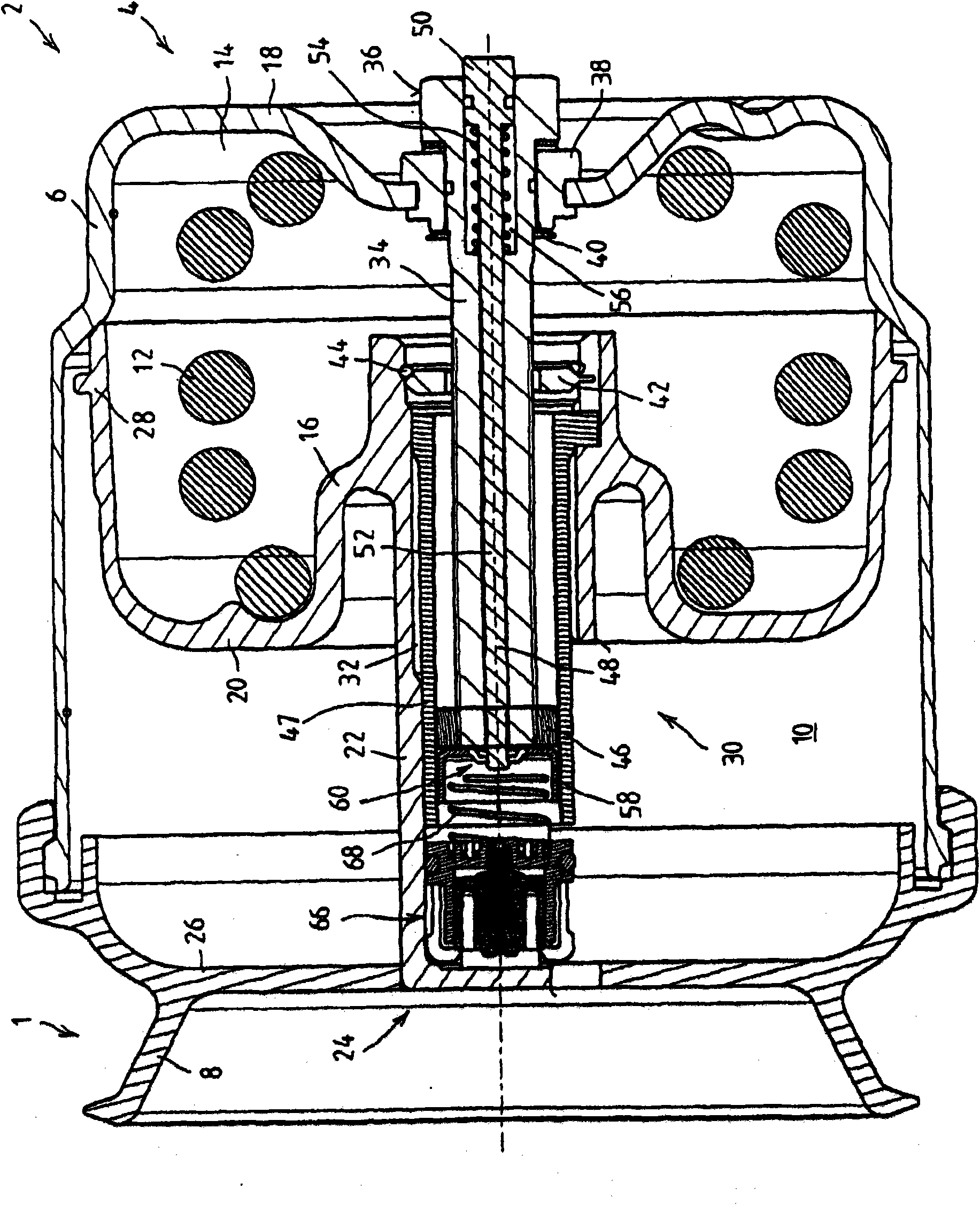
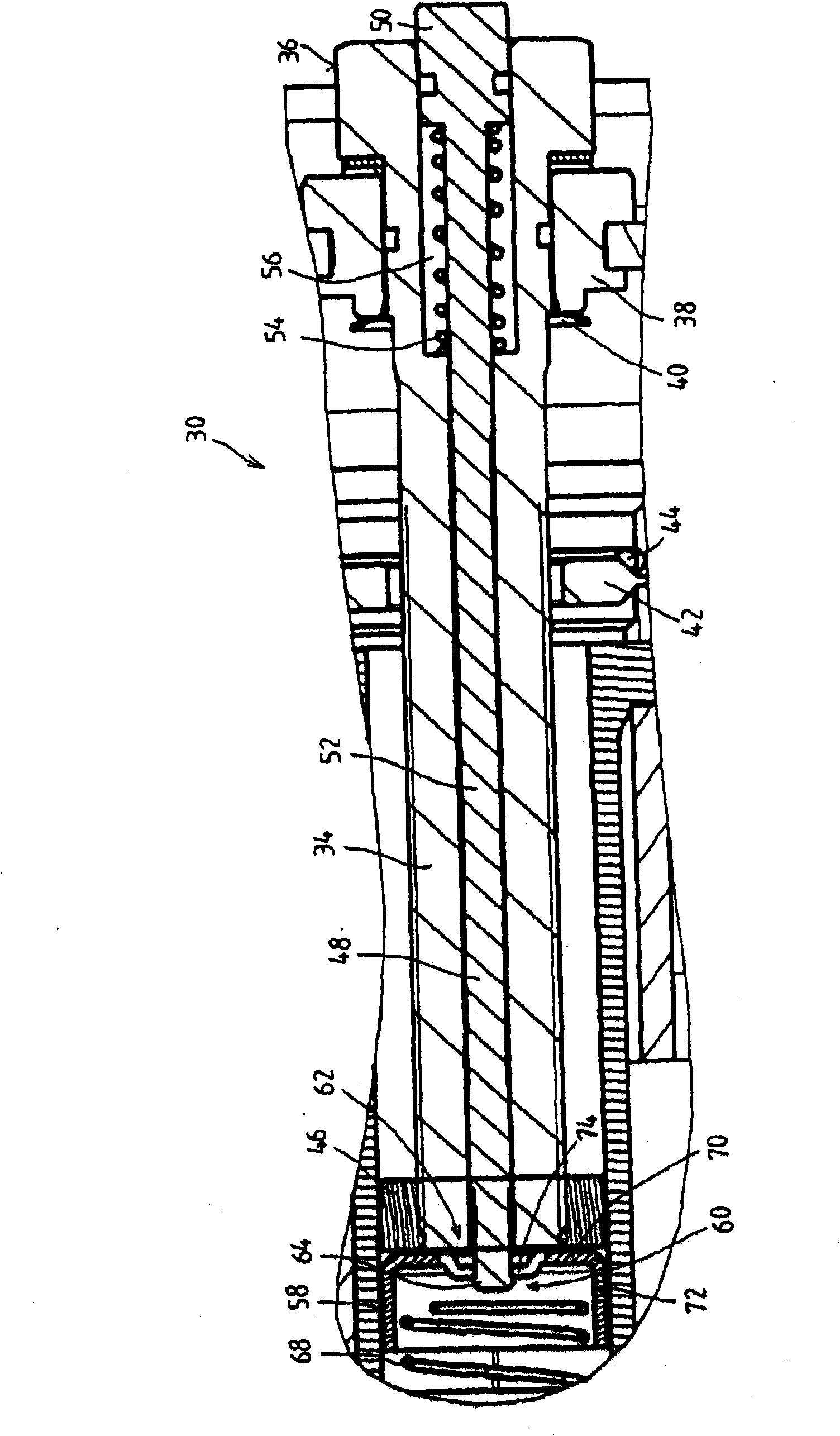
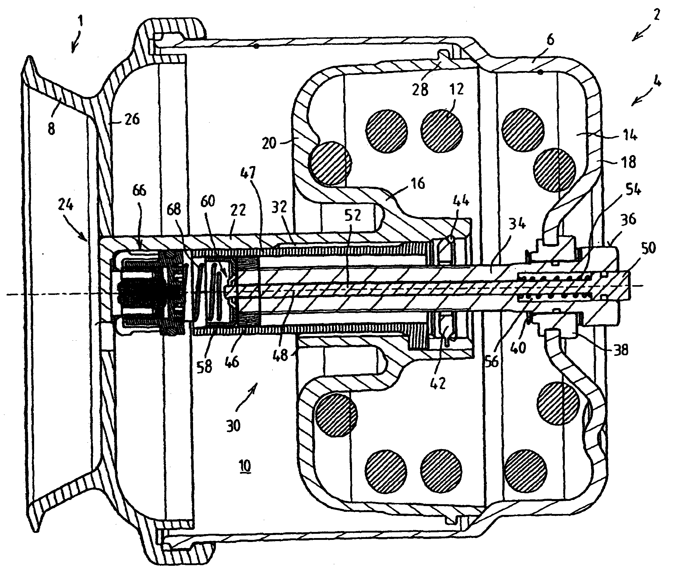
[0023] exist figure 1 shows a detail of a combined service brake cylinder and spring-charged brake cylinder 1 (combined brake cylinder) of a pneumatic or electro-pneumatic brake system of a commercial vehicle. It comprises a service brake system (not shown in the figure), which has a service brake cylinder with a housing, in which a pneumatically loadable service brake piston is guided, the service brake The brake piston actuates eg a disc brake of a commercial vehicle via a service brake piston rod.

[0024] Combination Cylinder 1 is also included in the figure 1 The spring energy storage brake device 2 visible in the figure has a spring energy storage brake cylinder 4 with a housing 6 on which a flange 8 is connected so that the housing 6 and the flange 8 constitutes a substantially closed unit. For example, a service brake cylinder can be attached to the flange 8 . In the housing 6, the spring-charged brake piston 16, which can be clamped by the pneumatic pressure in th...


PUM


Abstract

The invention relates to a spring-loaded brake cylinder (4) for vehicles, comprising at least one spring-loaded brake piston (16) that can be actuated by a pre-loaded spring (12) and is supported in a housing (6), said brake piston being delimited on one side by a spring-loaded brake chamber (10) and on the opposite side by a spring chamber (14) receiving the pre-loaded spring (12) and being connected to a spring-loaded brake piston rod (22), and further comprising a mechanical emergency release device (30) for the emergency release of the spring-loaded brake cylinder (4), wherein by means of the emergency release device (30) an axial displacement of the spring-loaded brake piston (16) against the prestress of the pre-loaded spring (12) can be brought about, and the emergency release device (30) comprises a threaded spindle (34), which is rotationally mounted on the housing (6) and in engagement with an axially movable transfer device (46) held non-rotatably in the emergency release device (30), wherein the transfer device (46) can be brought in contact with a contact surface (42) on the spring-loaded brake piston (16) for the emergency release of the spring-loaded brake cylinder (4), and further comprising an indicator device having an indicator rod (48) indicating the position of the spring-loaded brake piston (16), said rod traversing the threaded spindle (34) and being movable thereto in the axial direction, wherein a stop body (58) is disposed in the region of one end of the indicator rod (48), said body being engageable in the transfer device (46). According to the invention, the stop body (58) is positively connected to the indicator rod (48) by a detent connection (60) produced by means of an axial relative movement between the indicator rod (48) and the stop body (58).

Description

technical field [0001] The invention relates to a spring energy storage brake cylinder, which is used in particular in commercial vehicles. Background technique [0002] Such spring-charged brake cylinders usually have a housing, in which a spring-charged brake piston is guided, which divides the interior of the housing into a spring-charged brake that can apply pressure. Actuating chamber and a spring chamber for accumulating spring. The energy storage spring is arranged in the spring chamber in such a way that it biases the spring energy storage brake piston in the direction of the spring energy storage brake chamber. In order to move a stationary or braked vehicle provided with a spring-charged brake cylinder, the spring-charged brake chamber is charged with compressed air so that the spring-charged brake piston is displaced against the elastic force of the stored-charge spring. In this way, the brake device coupled with the spring-loaded brake piston is disengaged from...

Claims


Application Information

Patent Timeline
Patent Type & Authority Applications(China)
IPC IPC(8): B60T17/08F16D65/28
CPCB60T17/086Y10T29/49826
Inventor J·朗克托S·德鲁奥
Owner KNORR BREMSE SYST FUER NUTZFAHRZEUGE GMBH
Why Eureka
Eureka Blog
Learn More