
Automatic lathe for processing spanner

An automatic lathe and spindle technology, applied in the field of lathes, can solve problems such as high cost, influence of positioning accuracy, inertia of the spindle, etc., and achieve the effect of low cost, simple design and accurate positioning

Inactive Publication Date: 2010-08-11
ZHEJIANG YIYANG TOOL MFG
View PDF5 Cites 17 Cited by
  • Summary
  • Abstract
  • Description
  • Claims
  • Application Information

AI Technical Summary

Problems solved by technology

Now there are many methods for positioning the spindle of lathes, the more common one is to send pulse signals through the pulse generator to stop the stepping motor, thereby stopping the spindle; To the pulse generator and stepping motor, and the main shaft may still have inertia after positioning, and it will rotate, so the positioning accuracy will be affected

Method used


Image

  • Automatic lathe for processing spanner
  • Automatic lathe for processing spanner
  • Automatic lathe for processing spanner

Examples


Embodiment Construction

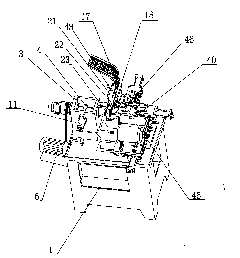
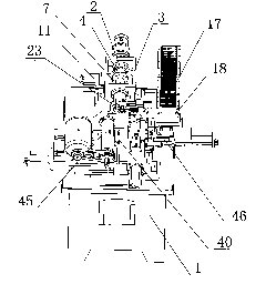
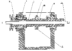
[0033] Such as Figure 1-6 As shown, the lathe includes a base 1. The base 1 is provided with a feeding system, a spindle system, a turning tool system 45 and a milling cutter system 46 for material processing. 2 Cross the box body 3 and fix it on the box body 3 through bearings. The front end of the main shaft 2 extends out of the box body 3 and is equipped with a clamping mechanism. And fixed on the middle part of the main shaft 2 by the flat key 49, the main shaft positioning ring 4 side is provided with a positioning groove 5, the rear end of the main shaft 2 is fixed with a pulley 50, the pulley 50 is connected to the motor 6 through the belt, and the motor 6 drives the main shaft 2 to rotate through the belt drive Main shaft 2 one side is provided with positioning system, and positioning system comprises positioning cylinder 11, and positioning cylinder 11 is fixed on the casing 3, and corresponds with main shaft positioning ring 4, and positioning block 7 is fixed on th...


PUM


Abstract

The invention relates to a lathe, in particular to an automatic lathe for processing a spanner. The lathe is characterized in that a positioning ring is installed on a principal shaft; a positioning groove is arranged on the lateral side of the positioning ring; a positioning block is pushed by a gas cylinder to be clamped in the clamping groove, at the same time, an inductive switch is induced to send out an induction signal to enable a spindle motor to stop running, and thereby the principal shaft can be positioned and stops running. The automatic lathe can position accurately, the positioning block is clamped in the positioning groove to enable the principal shaft to be firmly fixed, and the principal shaft can not be positioned inaccurately due to rotational inertia; and the automatic lathe is simple in design and low in cost.

Description

technical field [0001] The invention relates to a lathe, in particular to a lathe for processing wrenches. Background technique [0002] When the lathe is processing the wrench, it is necessary to use the turning tool to turn the hole on the wrench head, and use the milling cutter to mill the slot. When switching between various operations, it is necessary to accurately position the spindle to make it fast. Accurate stop. Now there are many ways to locate the spindle of a lathe, the more common one is to send a pulse signal through the pulse generator to stop the stepper motor, so that the spindle stops; but the disadvantage of this method is that the cost is high and it needs As far as the pulse generator and stepping motor are concerned, the spindle may still have inertia after positioning and will rotate, which will affect the positioning accuracy. Contents of the invention [0003] In view of the above problems, the purpose of the present invention is to provide a si...

Claims


Application Information

Patent Timeline
Patent Type & Authority Applications(China)
IPC IPC(8): B23P23/02
Inventor 杨春炜
Owner ZHEJIANG YIYANG TOOL MFG
Learn More