Combination of fan cover assembly and extinguishing switch

A technology of flameout switch and fan cover, which is applied in the direction of engine control, machine/engine, mechanical equipment, etc. It can solve the problems of easy damage to the appearance of fan cover components, unreliable installation of flameout switch, and difficult to accurately control the interference, so as to achieve the goal of dismantling The effect of easy installation, simple structure, and easy processing

Inactive Publication Date: 2010-08-11
力帆科技(集团)股份有限公司
View PDF4 Cites 0 Cited by
  • Summary
  • Abstract
  • Description
  • Claims
  • Application Information

AI Technical Summary

Problems solved by technology

Since the fan cover assembly is a stamping part and the flameout switch is an injection molding part, the interference between the two is not easy to control accurately
If the interference is too small, the installation of the flameout switch is not reliable, and it is easy to slip out of the spline hole; if the interference is too large, it will increase the difficulty of assembly, and the flameout switch is easily damaged by tapping the flameout switch with a rubber hammer
In order to prevent the flameout switch from falling off, a one-way anti-retreat groove is generally designed on the flameout switch. This groove is clamped with a rectangular spline, and it is very difficult to disassemble. On the one hand, it is not convenient for maintenance; Appearance

Method used


Image

  • Combination of fan cover assembly and extinguishing switch
  • Combination of fan cover assembly and extinguishing switch
  • Combination of fan cover assembly and extinguishing switch

Examples


Embodiment Construction

[0018] Below in conjunction with accompanying drawing and embodiment the present invention will be further described:

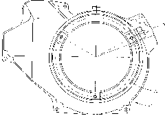
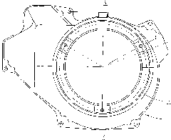
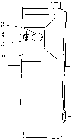
[0019] Such as Figure 1 to Figure 8 As shown, the present invention is made up of fan cover assembly 1, flameout switch 2, screw 3 and nut 4, and the shape and structure of fan cover assembly 1 adopts prior art, does not repeat them here. A circular casing 1a is integrally formed on the fan casing assembly 1, and the casing 1a is as figure 1 , 2 There is a circular positioning hole 1b for inserting the flameout switch in the upper right part of the circle shown. The positioning hole 1b is a light hole, and the wall of the positioning hole 1b extends toward the center to form 2 to 4 limiting protrusions 1c evenly distributed on the circumference. In this embodiment, the number of limiting protrusions 1c is preferably There are 3 pieces, and each limiting tab 1c is rectangular, or arc-shaped or other suitable shapes. An assembly hole 1d is also opened on t...


PUM


Abstract

The invention relates to a combination of a fan cover assembly and an extinguishing switch. A positioning hole for inserting the extinguishing switch is arranged on a cover shell of the fan cover assembly, a round lug boss is arranged at the lower part of the extinguishing switch which is provided with a supporting ear in the middle, the positioning hole on the cover shell is a light hole and is provided with a limit protruding sheet on the hole wall, an assembly hole is arranged beside the positioning hole, the round lug boss of the extinguishing switch is inserted in and tightly matched with the positioning hole of the cover shell, an opening arranged on the round lug boss and the limit protruding sheet on the hole wall of the positioning hole are clamped, the supporting ear of the extinguishing switch is provided with a via hole, and a screw penetrates through the via hole arranged on the supporting ear and the assembly hole on the cover shell and locked by a nut. The invention has simple structure and easy processing and manufacture, effectively lowers the assembly difficulty of the extinguishing switch, greatly improves the assembly efficiency and prevents the extinguishing switch and the fan cover assembly from being damaged and discarded in the disassembly process while ensuring the extinguishing switch is convenient to disassemble and the extinguishing switch is firmly mounted.

Description

technical field [0001] The invention belongs to the technical field of gasoline engines, and in particular relates to a flameout switch installation structure of a general gasoline engine. Background technique [0002] The flameout switch is an important component to control the flameout of the general gasoline engine, and is usually installed on the fan cover assembly. At present, the assembly hole on the flameout switch and the fan cover assembly is an interference fit, that is, a rectangular spline hole is punched out on the casing of the fan cover assembly, and the flameout switch is knocked into the spline hole by a rubber hammer. Since the fan cover assembly is a stamping part and the flameout switch is an injection molding part, the interference between the two is difficult to accurately control. If the interference is too small, the installation of the flameout switch will not be reliable, and it will easily slip out of the spline hole; if the interference is too la...

Claims


Application Information

Patent Timeline
Patent Type & Authority Applications(China)
IPC IPC(8): F02D11/04
Inventor 杨豪
Owner 力帆科技(集团)股份有限公司
Why Eureka
Try Eureka