Thunder and lightning locator with sound sensors and locating method thereof
What is AI technical title?
AI technical title is built by Patsnap AI team. It summarizes the technical point description of the patent document.
A sound sensor and lightning location technology, applied in the field of meteorological detection, can solve the problems of large equipment investment, single function, complex principle, etc.
Inactive Publication Date: 2010-08-11
CMA METEOROLOGICAL OBSERVATION CENT
View PDF0 Cites 31 Cited by
Summary
Abstract
Description
Claims
Application Information
AI Technical Summary
This helps you quickly interpret patents by identifying the three key elements:
Problems solved by technology
Method used
Benefits of technology
Problems solved by technology
[0003] The purpose of the present invention is to provide a lightning locator with multiple sound sensors and its positioning method, to solve the technical problems of complex principles, large equipment investment and single function of the existing lightning measurement method
Method used
Image
Click on the blue label to locate the original text in one second.
Reading with bidirectional positioning of images and text.
Examples
Embodiment 1
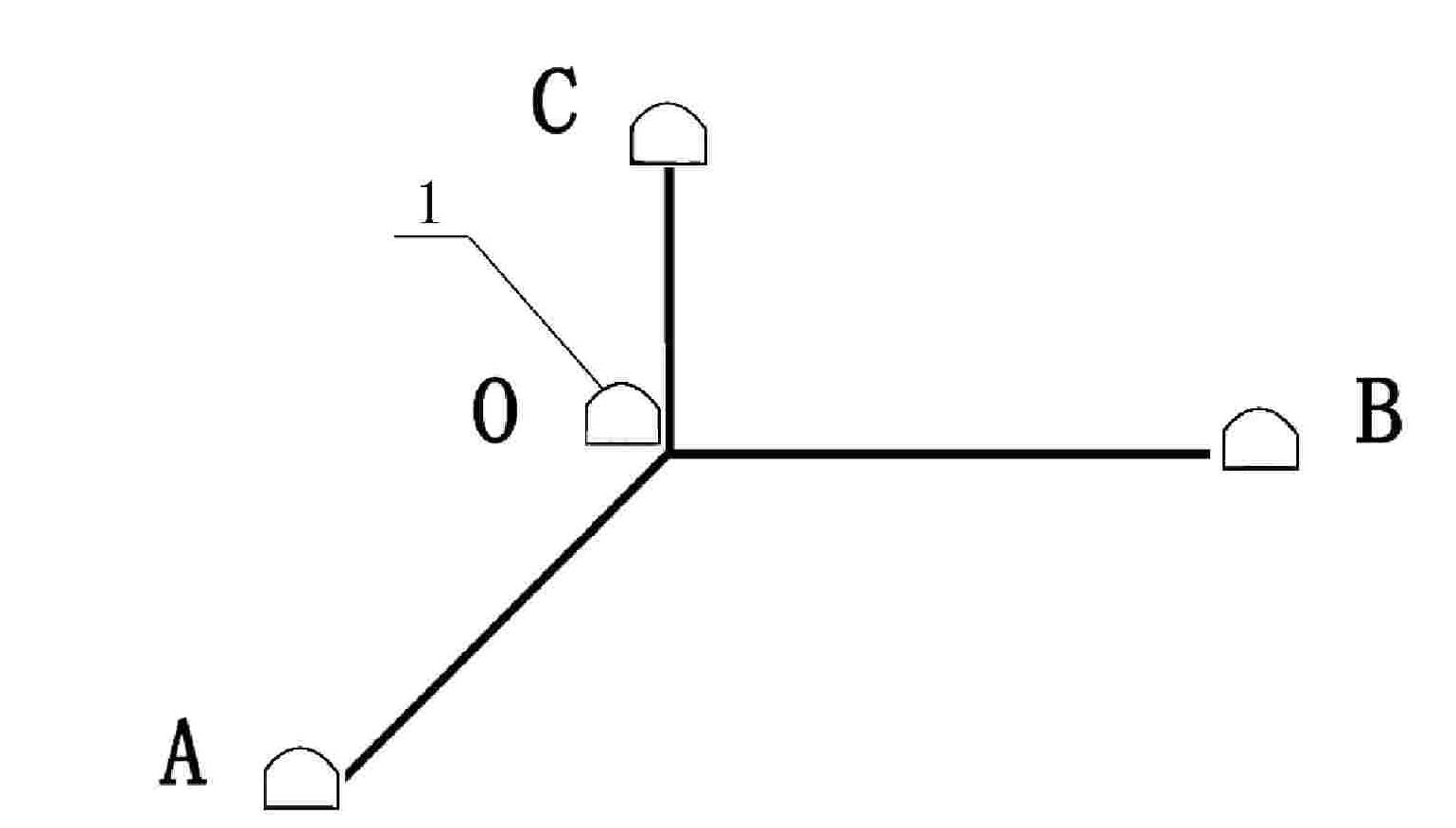
[0053] Example one see Figure 1-Figure 4 As shown, the lightning positioning method with multiple sound sensors is characterized by:
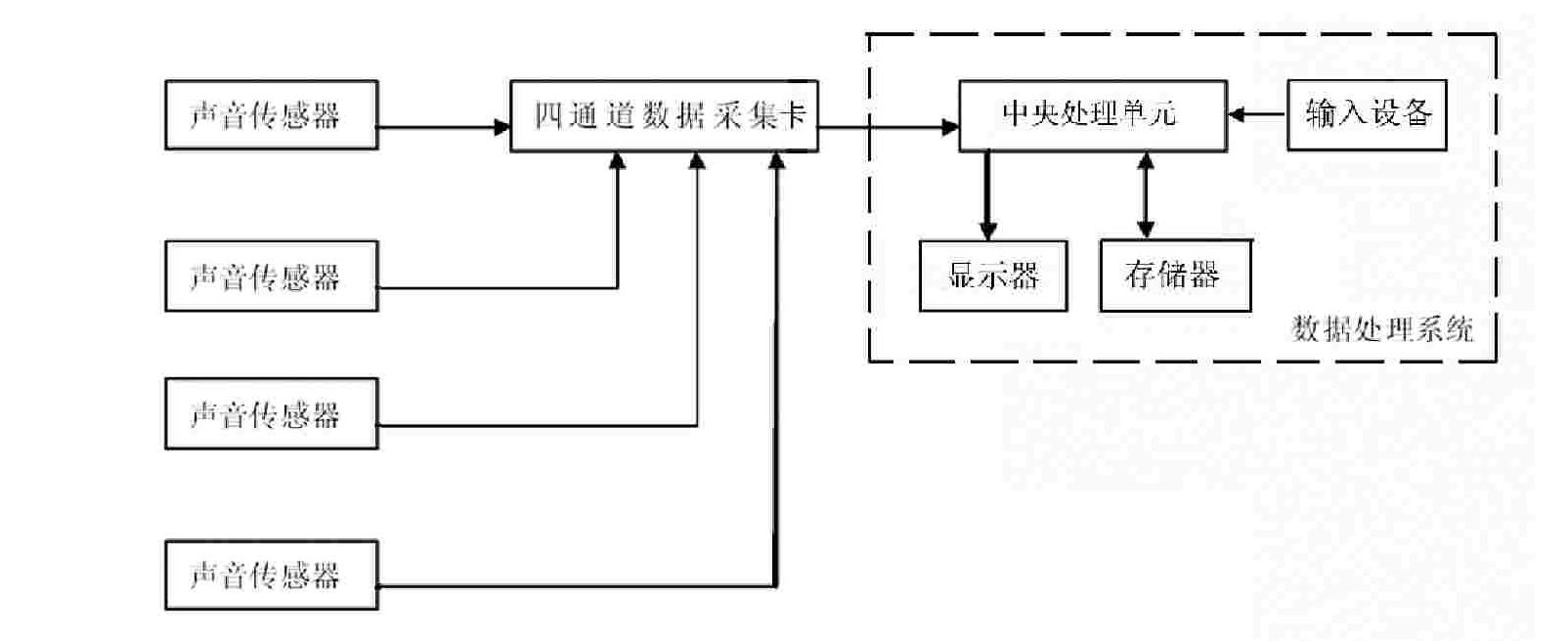
[0054] Step 1. The unknown lightning coordinate is point P, and a sound sensor is arranged at each of the four spatial observation points O, A, B, and C. The sound sensor is a microphone or a recorder, and the sampling speed is ≥30 microseconds. The sound sensor 1 is a microphone or Audio recorder, sampling speed ≥30 microseconds, light sensor 2 is a wide-angle camera, four sound sensors are connected to the four signal input channels of a four-channel data acquisition card, and the output of the four-channel data acquisition card is connected to the signal input of the data processing system Interface connection
[0055] The coordinates of the four observation points in space are O(x o , Y o ,z o ), A(x a , Y a ,z a ), B(x b , Y b ,z b ), C(x c , Y c ,z c ), then the distances of the three spatial observation points A, B, and C to point O are fix...
Embodiment 2
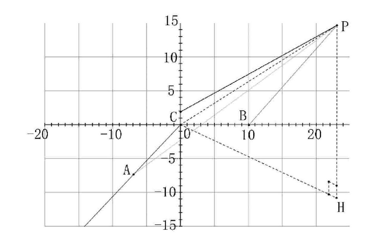
[0080] See the second embodiment Figure 5 , Image 6 As shown, this multiple sound sensor lightning positioning method,
[0081] Step 1. The unknown lightning coordinate is point P. Three sound sensors and one light sensor are arranged at four observation points O, A, B, and C. The three sound sensors are located at the same altitude, and the three ground connections can form one Right-angled triangle, the light sensor is located anywhere in the right-angled triangle, three sound sensors and one light sensor are connected to the three signal input channels of a multi-channel data acquisition card, and the output of the multi-channel data acquisition card is connected to the signal of the data processing system Input interface connection;
[0082] The coordinates of the four observation points are O(x o , Y o ,z o ), A(x a , Y a ,z a ), B(x b , Y b ,z b ), C(x c , Y c ,z c ), then the distances of the three spatial observation points A, B, and C to point O are fixed values: AO, BO,...
PUM
Abstract
The invention relates to a thunder and lightning locator with sound sensors and a locating method thereof. The thunder and lightning locator comprises four sound sensors, a four-passage data acquisition card and a data processingsystem, wherein the four sound sensors are distributed on four observing points; when thunder and lightning occur, the sound sensors positioned on the four space observing points respectively record the thunder reaching time of the observing points; four groups of time data are converted from A / D (analog to digital) by the four-passage data acquisition card and then transmitted to the data processingsystem; the data processingsystem solves the difference of the thunder reaching time of three space observing points through logical operation and computes the difference of the distances of the three space observing points according to the propagation speed of sound in the air; and a coordinate of a thunder and lightning generation position is determined according to an equation set and a principle that a point can be determined by intersecting three hyperboloids in space. The invention ensures high measurement precision, also simplifies a locating measurement method, reduces the hardware requirements and the equipment cost, realizes the accurate automatic locating of the thunder and lightning and can be widely used in the field of meteorological sounding.
Description
Technical field [0001] The invention relates to the technical field of weather detection, in particular to a lightning positioning method. Background technique [0002] At present, the lightning positioning methods generally recognized internationally can be roughly divided into five types. The first is to improve the gated magnetic pulse orientation method, such as the widely used ground flash directional instrument (DF), which can identify the LF (low frequency) frequency band radiated electromagnetic field waveforms of typical ground lightning, and determine the peak value and orientation of the discharge waveform . Multi-station DF network can determine the location of lightning. The second is the long baseline TOA (Time of Arrival) technology that works in the LF band, such as the Lightning Location and Tracking System (LPATS). The third is the interferometer method that works in the VHF (very high frequency) frequency band. Its characteristic is that it can detect cloud ...
Claims
Application Information
Patent Timeline
Application Date:The date an application was filed.
Publication Date:The date a patent or application was officially published.
First Publication Date:The earliest publication date of a patent with the same application number.
Issue Date:Publication date of the patent grant document.
PCT Entry Date:The Entry date of PCT National Phase.
Estimated Expiry Date:The statutory expiry date of a patent right according to the Patent Law, and it is the longest term of protection that the patent right can achieve without the termination of the patent right due to other reasons(Term extension factor has been taken into account ).
Invalid Date:Actual expiry date is based on effective date or publication date of legal transaction data of invalid patent.

