
Color split optical element and image panel device

A technology for optical components and color separation, applied in the direction of optical components, optics, diffraction gratings, etc., can solve the problems of high construction costs, reduced light energy utilization efficiency, cumbersome process of dye-based color filters, etc.

Active Publication Date: 2010-08-11
IND TECH RES INST
View PDF2 Cites 26 Cited by
  • Summary
  • Abstract
  • Description
  • Claims
  • Application Information

AI Technical Summary

Problems solved by technology

When the system uses a traditional dye-based color filter, because each image pixel of the color filter can only present a single color in the three primary colors of red, green and blue, generally about two-thirds of the energy of incident white light is absorbed, thereby reducing It reduces the efficiency of light energy utilization and reduces the battery life of portable electronic products
In addition, the process of dye-based color filters is cumbersome, which consumes process materials, and the cost of products and factory construction remains high.

Method used


Image

  • Color split optical element and image panel device
  • Color split optical element and image panel device
  • Color split optical element and image panel device

Examples


Embodiment Construction

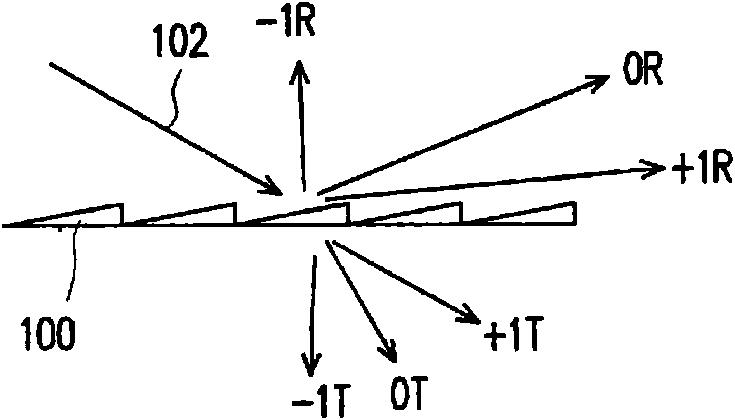
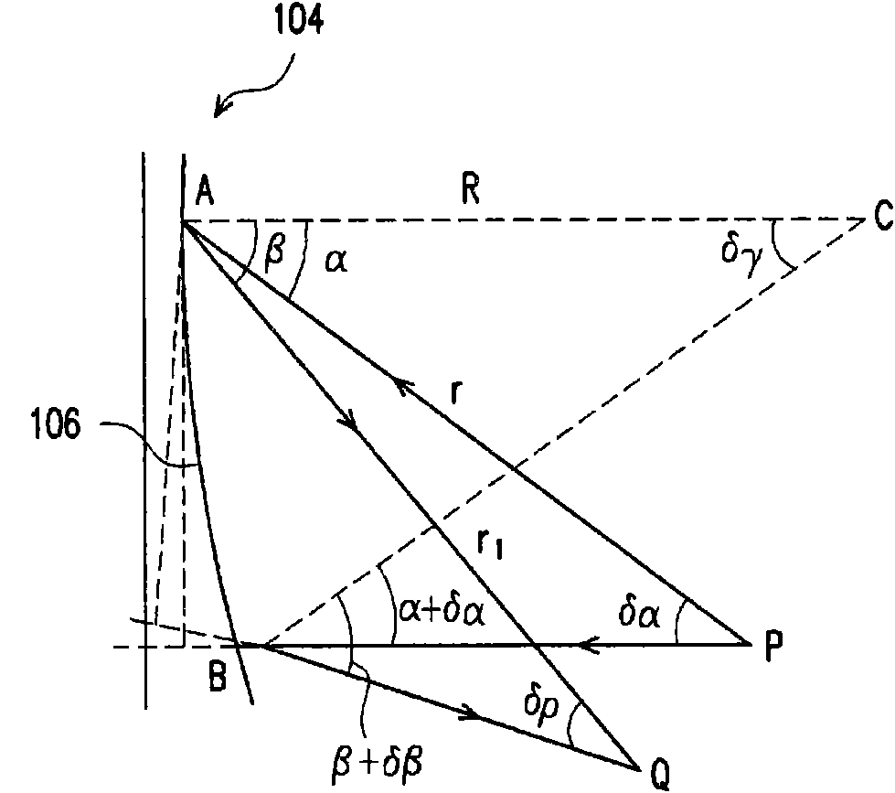
[0075] Regarding the optical phenomena of optical elements, the present invention considers periodic optical micro-nano structures. By adjusting the relative angle of the incident light and the slope of the periodic micro-nano structure, the direction of the diffracted light and the facet of the optical tooth (Groove) are taken as When the refraction directions of the refraction plane are the same, the diffraction optical efficiency can reach the maximum in the diffraction direction (or the refraction direction of Facet) at this time. The present invention can integrate light refraction and diffraction optimization functions, and design an integrated device to make incident light sources composed of different wavelengths perform beam splitting and color separation at the same time. The light source splits the beams according to the same intensity to form an array sub-light source. For example, it is also a beam splitting function. At the same time, the light beams composed of di...


PUM


Abstract

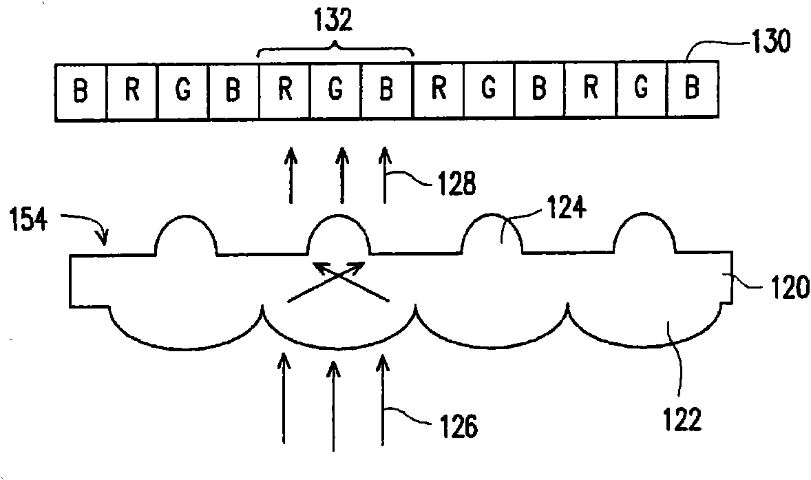
The invention discloses a color split optical element and an image panel device. The color separating optical element has an integrated double-face structure, and each face comprises a micro / nano structure. The optical element can split beams and colors for an incident light source containing different wavelengths. In a space, the primary incident light source is equally split into array beams according to the intensity, and meanwhile the beams with different wavelengths are split into sub light sources according to the wavelengths to form the color split transmission function of color arrays. The optical element of adjustable light wave colors can convert a broadband incident light source into sub beams of array split colors (split waves) and split beams.

Description

Technical field [0001] The present invention relates to a color separation optical element, and in particular to an optical element having both beam splitting and color separation effects. Background technique [0002] A digital image is composed of multiple pixels in an array to present an image. In addition, for color images, each pixel is, for example, composed of three sub-pixel colors of the three primary colors of red, green and blue, so as to present the desired color. Generally, three sub-pixel colors of red, green and blue are generated, and for each sub-pixel, a color filter color dye corresponding to the required color beam needs to be set. In this way, for the incident light source of white light, its use efficiency will be reduced to 1 / 3, and about 2 / 3 of other non-corresponding color beams will be absorbed. [0003] For flat panel display applications, the backlight of TFT-LCD must be matched with liquid crystal for light field brightness modulation and dye-type col...

Claims


Application Information

Patent Timeline
Patent Type & Authority Applications(China)
IPC IPC(8): G02B27/44G02B27/10G02B5/18
Inventor 林晖雄廖启宏
Owner IND TECH RES INST
Learn More