
A light emitting display device and a drinving method thereof

A technology of light-emitting display and equipment, applied in the direction of electroluminescence light source, light source, electric light source, etc.

Inactive Publication Date: 2010-08-11
SAMSUNG DISPLAY CO LTD
View PDF7 Cites 38 Cited by
  • Summary
  • Abstract
  • Description
  • Claims
  • Application Information

AI Technical Summary

Problems solved by technology

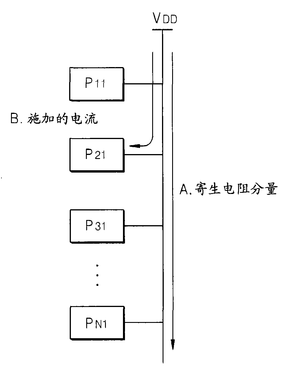
[0008] The present invention provides a light-emitting display device and a driving method thereof, thereby solving the problem that the power supply voltage supplied to each pixel varies depending on the position of the pixel due to the parasitic resistance component of the wiring or by the voltage applied to each pixel. circuit current according to the increased voltage drop of the panel size resulting in

Method used


Image

  • A light emitting display device and a drinving method thereof
  • A light emitting display device and a drinving method thereof
  • A light emitting display device and a drinving method thereof

Examples


Embodiment Construction

[0023] In the following detailed description with reference to the accompanying drawings, there are shown and described, by way of illustration only, certain exemplary embodiments of the present invention. As those skilled in the art will appreciate, the invention may be embodied in many different forms and should not be construed as limited to the embodiments set forth herein. Accordingly, the scope of the invention is to be defined by the claims and their equivalents. The terms used herein should be understood as having meanings and concepts consistent with the technical aspects of the present invention, so as to describe the present invention in a manner that enables those of ordinary skill in the art to make and use the present invention.

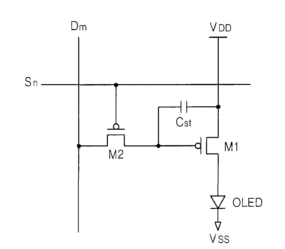
[0024] figure 1 is a schematic diagram showing a pixel circuit of a conventional light-emitting display device.

[0025] A pixel circuit of a light emitting display device includes a light emitting device (for example, an organic ligh...


PUM


Abstract

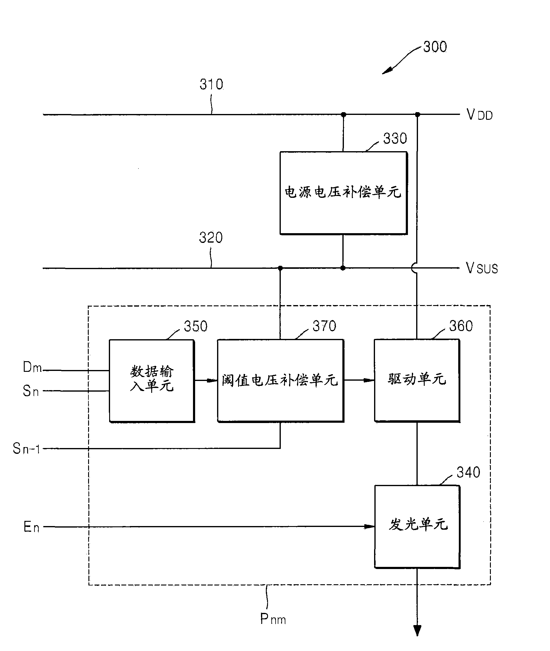
A light emitting display apparatus and method for driving same is provided. In one embodiment, the light emitting display apparatus includes a plurality of pixel circuits, wherein each of the pixel circuits includes a light emitting device, a driving transistor having a first electrode coupled to the light emitting device and a second electrode coupled to a first power voltage supply line, a compensation capacitor having a first terminal coupled to a gate electrode of the driving transistor, a first switching device configured to provide a voltage from the second power voltage supply line to a second terminal of the compensation capacitor in response to an initialization control signal, and a second switching device configured to provide a data signal to the second terminal of the compensation capacitor in response to a scan signal, wherein the first power voltage supply line and the second power voltage supply line are electrically coupled.

Description

[0001] This application claims priority and benefit from Korean Patent Application No. 10-2009-0009860 filed in the Korean Intellectual Property Office on February 6, 2009, the entire disclosure of which is hereby incorporated by reference. technical field [0002] The present invention relates to a light-emitting display device, and more specifically, to an organic light-emitting display device and a driving method thereof. Background technique [0003] An organic light emitting display device is a display device that displays an image by applying current or voltage to an organic light emitting diode (OLED) to emit light by electrically exciting a fluorescent organic compound material. [0004] An OLED includes an anode layer, an organic thin layer and a cathode layer. The organic thin layer of the OLED has a multi-layer structure including an emissive material layer (EML), an electron transport layer (ETL) and a hole transport layer (HTL) to improve the balance between ele...

Claims


Application Information

Patent Timeline
Patent Type & Authority Applications(China)
IPC IPC(8): G09G3/32H05B44/00
CPCG09G2300/0852G09G2300/0861G09G2320/0233G09G3/3233G09G2300/0819G09G2330/02G09G2320/0223G09G3/30G09G3/20
Inventor 金世镐郭源奎
Owner SAMSUNG DISPLAY CO LTD
Learn More