
Cylinder rinsing device

A technology for cleaning devices and rollers, applied in cleaning methods and utensils, cleaning methods using tools, dissolving and other directions to achieve the effects of preventing wrinkling, easy adjustment, and improving cleaning efficiency

Inactive Publication Date: 2010-08-11
JPE
View PDF3 Cites 5 Cited by
  • Summary
  • Abstract
  • Description
  • Claims
  • Application Information

AI Technical Summary

Problems solved by technology

[0014] The present invention is proposed to solve the problems in the above-mentioned prior art. The purpose of the present invention is to provide a drum cleaning device, which enables the pressure pad to be pressed against the pad mounting plate and held firmly without Rotate and lift to prevent fluctuations. At the same time, it is easy to install the pressure pad, which will not cause uneven wiping, will not push the detection roller for detecting the diameter of the cleaning cloth during the cleaning cloth winding, and can simply install the roller shaft on the In the bearings on the plate, a dry cloth can be used

Method used


Image

  • Cylinder rinsing device
  • Cylinder rinsing device
  • Cylinder rinsing device

Examples


Embodiment Construction

[0105] Embodiments of the present invention will be described below with reference to the drawings.

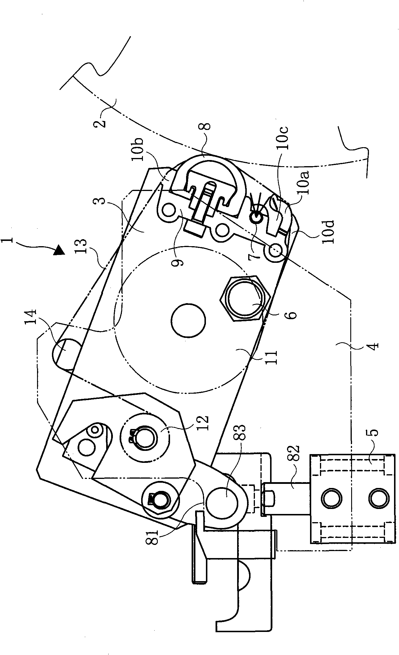
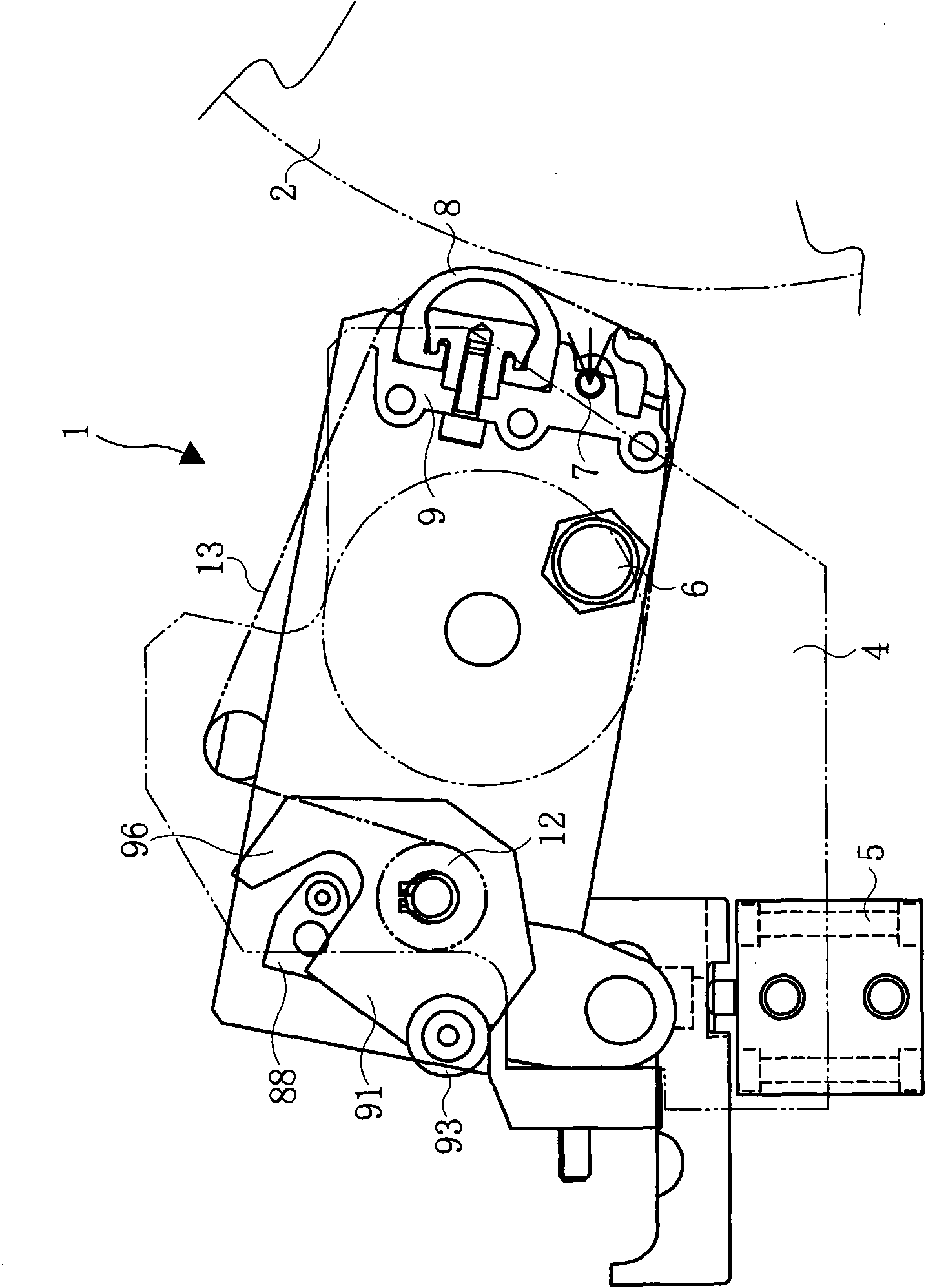
[0106] Figure 1-Figure 3 The cylinder cleaning device 1 of the first embodiment shown is disposed opposite to the blanket cylinder 2 to be cleaned, and the cylinder cleaning device 1 is composed of a pair of plates 3 on which a roller of a cleaning cloth is detachably mounted, and fixed outside the plates 3. The frame 4 provided on the frame of the printing machine constitutes a frame, and an air cylinder 5 as a source of a pressing means is provided on one frame 4 .

[0107] Through this air cylinder 5 , the cylinder cleaning device 1 rotates around the rotary shaft 6 , and plays a role of making it contact with and separate from the blanket cylinder 2 .

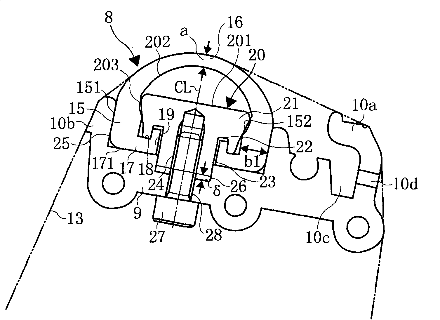
[0108] The pushing part is arranged on the opposite side of the rubber printing cylinder 2, such as image 3 As shown, it consists of a pad mounting plate 9 for mounting a pressing pad 8 as a pressing member, and guide p...


PUM


Abstract

Intended is to provide a cylinder rinsing device having a novel constitution thereby to prevent the flapping phenomenon of a pressure pad and to mount the pressure pad easily. The cylinder rinsing device comprises a rinsing cloth winding roll having a pressure pad made of an elastic member for pushing a piece of rinsing cloth to a cylinder surface. A pressure pad (8) is fixed between a pad mounting plate (9) and a pad holding bar (20) and formed of an elastic material into a semicircular shape. The pressure pad (8) is made thin at the pushing portion of its central portion (16) and thick at the base portions (15) of its two end portions, and the base portions (15) have retained portions (17) to be pushed by the pad holding bar (20). The pressure pad (8) has an inward inclined face made thicker in the widthwise direction by inclining the inner faces (152) of the base portions (15) inward to the bottom face. The pad mounting plate (9) extends in the trunk length direction of the cylinder, and has such a recess (25) formed on the side to confront the cylinder as to receive the pressure pad. The pad holding bar (20) has such an inward inclined face (203) on the side wall to contact the inner face of the pressure pad (8) as is inclined inward in a converging state toward the bottom portion. The inward inclined face (203) of the pad holding bar (20) is pushed to abut on the inward inclined face of the pressure pad (8), and the inward inclined faces of the base portions (15) of the pressure pad (8) are pushed onto the wall face of the pad mounting plate (9) on the side of the recess (25).

Description

technical field [0001] The present invention relates to a cylinder cleaning device for cleaning the surface of a printing press cylinder such as an offset printing cylinder of an offset printing machine, and particularly relates to the following cylinder cleaning device: including the shape of the pressure pad required for cleaning the cylinder, the fixed size winding of the cleaning cloth, the cleaning cloth For the installation of the supply and take-up rollers, use a dry cloth that is moistened by spraying the cleaning solution on the cleaning cloth just before cleaning. Background technique [0002] In the past, as a cylinder cleaning device for cleaning offset cylinders, pressure cylinders, etc., the following devices are known: a cleaning cloth made of non-woven fabric can be moved in contact with the surface of the cylinder at a pressing part that can be contacted / separated from the surface of the cylinder. During the cleaning operation, the cleaning cloth is moved in...

Claims


Application Information

Patent Timeline
IPC IPC(8): B41F35/06B01F3/04
CPCB41F35/06B41F35/04B41P2235/24B41F35/00B08B1/00B08B1/008B41P2235/246B08B1/30
Inventor 熊木恒夫桥本邦彦宫崎洁星野满夫
Owner JPE
Learn More