Composite membrane for super straight solar cell, process for producing the composite membrane for super straight solar cell, composite membrane for substraight solar cell, and process for producing the composite membrane for substraight solar cell

A solar cell, super-straight technology, applied in the field of composite films, which can solve the problems of increased reflected light and decreased reflectivity

Inactive Publication Date: 2010-08-11
MITSUBISHI MATERIALS CORP
View PDF14 Cites 20 Cited by
  • Summary
  • Abstract
  • Description
  • Claims
  • Application Information

AI Technical Summary

Problems solved by technology

It is presumed that this is because a void is formed between the reflective film and the substrate, and light is repeatedly reflected inside the void, resulting in a decrease in reflectance.
In addition, it is speculated that when the reflected light passing through the hole enters the substrate at an incident angle larger than the critical angle, the reflected light is totally reflected at the interface between the hole and the substrate, and the reflected light for this total reflection increases, so the reflectance reduce

Method used


Image

  • Composite membrane for super straight solar cell, process for producing the composite membrane for super straight solar cell, composite membrane for substraight solar cell, and process for producing the composite membrane for substraight solar cell
  • Composite membrane for super straight solar cell, process for producing the composite membrane for super straight solar cell, composite membrane for substraight solar cell, and process for producing the composite membrane for substraight solar cell
  • Composite membrane for super straight solar cell, process for producing the composite membrane for super straight solar cell, composite membrane for substraight solar cell, and process for producing the composite membrane for substraight solar cell

Examples


Embodiment approach 1

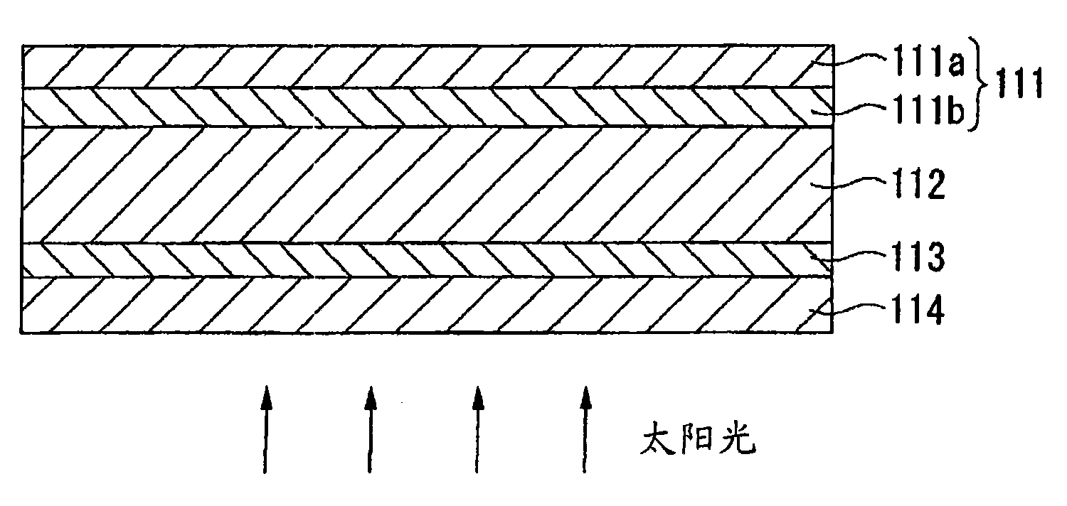
[0147] Ultra-straight thin-film solar cells are usually figure 1 As shown, a second transparent conductive film 111b is further formed on a layer formed by laminating a first transparent conductive film (transparent conductive film on the incident side of light) 113 and a photoelectric conversion layer 112 on a substrate 114 in this order, A conductive reflective film 111a is formed on the second transparent conductive film 111b.

[0148] Embodiment 1 of the present invention relates to an ultra-straight thin-film solar cell including two layers of a second transparent conductive film 111b formed on the photoelectric conversion layer 112 and a conductive reflective film 111a formed on the second transparent conductive film 111b. Composite Membrane 111.

[0149] In the composite film 111 according to Embodiment 1 of the present invention, the second transparent conductive film 111b is formed by applying a composition for a transparent conductive film containing conductive oxid...

Embodiment approach 2

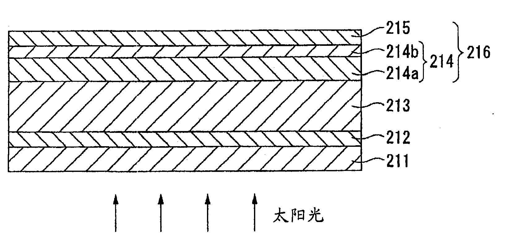
[0201] Ultra-straight thin-film solar cells usually have a first transparent conductive film (transparent conductive film on the incident side of light) and a photoelectric conversion layer stacked on the substrate in this order, and then a second transparent conductive film is formed on the photoelectric conversion layer. A structure in which a conductive reflective film is formed on the second transparent conductive film.

[0202] Embodiment 2 of the present invention relates to a composite film for an ultra-straight solar cell, which has a second transparent conductive film formed on a photoelectric conversion layer of an ultra-straight solar cell, and a conductive film formed on the second transparent conductive film. Sexual reflective film.

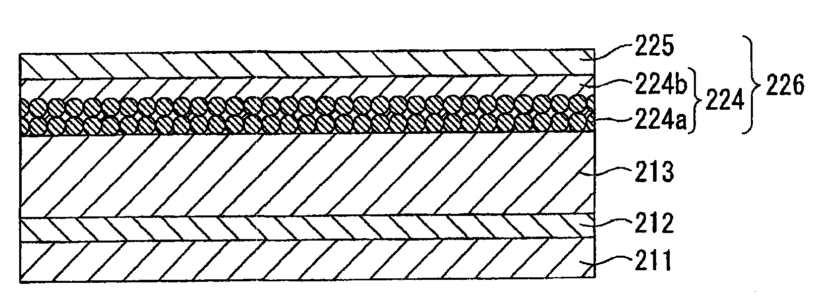
[0203] figure 2 It is a figure which schematically shows the cross section of the composite membrane which concerns on Embodiment 2 of this invention. The characteristic structure of the composite membrane 216 according to Embodim...

Embodiment approach 3

[0259] Substraight solar cells are usually as Figure 4 As shown, it has a structure in which a composite film 312 is formed on a substrate 311, and a photoelectric conversion layer 313 and a first transparent conductive film (transparent conductive film on the incident side of light) 314 are arranged on the composite film 312. A structure formed by stacking layers in sequence. The composite film 312 has a conductive reflective film 312a formed on the base material 311, and a second transparent conductive film 312b formed on the conductive reflective film 312a.

[0260] Embodiment 3 of the present invention relates to a composite film 312 for a substraight solar cell, which has a conductive reflective film 312a formed on a substrate 311 and a second transparent conductive film 312b formed on the conductive reflective film 312a. Floor.

[0261] In the composite film 312 according to Embodiment 3 of the present invention, the conductive reflective film 312a is formed by coatin...


PUM

PropertyMeasurementUnit
diameteraaaaaaaaaa
particle diameteraaaaaaaaaa

Abstract

This invention provides a composite membrane for a super straight solar cell or for a substraight solar cell. The composite membrane comprises a transparent electroconductive film and an electroconductive reflective film. The transparent elctroconductive film is formed by coating a composition or dispersion liquid, for a transparent electrocondutive film, containing fine particles of an electroconductive oxide by a wet coating method. The electroconductive reflective film is formed by coating a composition, for en electroconductive reflective film, containing metallic nanoparticles by a wet coating method. The average diameter of pores, which appear on a photoelectric converting layer-side or transparent electroconductive film-side contact face of the electroconductive reflective film, isnot more than 100 nm. The average depth at which the pores are located is not more than 100 nm. The number density of the pores is not more than 30 pores / [mu]m2.

Description

technical field [0001] The present invention relates to a composite film having two layers of a transparent conductive film and a conductive reflective film, and a method for producing the same. More specifically, it relates to a thin-film solar cell suitable for use in a super straight type solar cell or a substraight type solar cell Composite film and its manufacturing method. [0002] This application is directed to Japanese patent application No. 2007-236546 filed on September 12, 2007, Japanese patent application No. 2008-205849 filed on August 8, 2008, and Japanese patent application filed on August 8, 2008 Application No. 2008-205862, Japanese Patent Application No. 2008-205867 filed on August 8, 2008, Japanese Patent Application No. 2008-205870 filed on August 8, 2008, filed on September 2, 2008 Japanese Patent Application No. 2008-224497, Japanese Patent Application No. 2008-224499 filed on September 2, 2008, Japanese Patent Application No. 2008-224508 filed on Septe...

Claims


Application Information

Patent Timeline
Patent Type & Authority Applications(China)
IPC IPC(8): H01L31/04
CPCY02E10/52H01L31/02168H01L31/02366H01L31/0527Y02E10/548Y02E10/50H01L31/03921H01L31/022466H01L31/022475H01L31/022483H01L31/1884H01L31/056
Inventor 山崎和彦林年治荒井将英小川怜子高田佳明
Owner MITSUBISHI MATERIALS CORP
Why Eureka
Try Eureka