
Ultrasonic hand washing device

A hand washing device and ultrasonic technology, which are applied to household appliances, sanitary equipment, chemical instruments and methods, etc., can solve problems such as hidden dangers of sanitation and safety, poor washing effect, etc., and achieve high sanitation and safety, good washing effect and simple structure. Effect

Inactive Publication Date: 2010-08-18
姚建梁
View PDF4 Cites 2 Cited by
  • Summary
  • Abstract
  • Description
  • Claims
  • Application Information

AI Technical Summary

Problems solved by technology

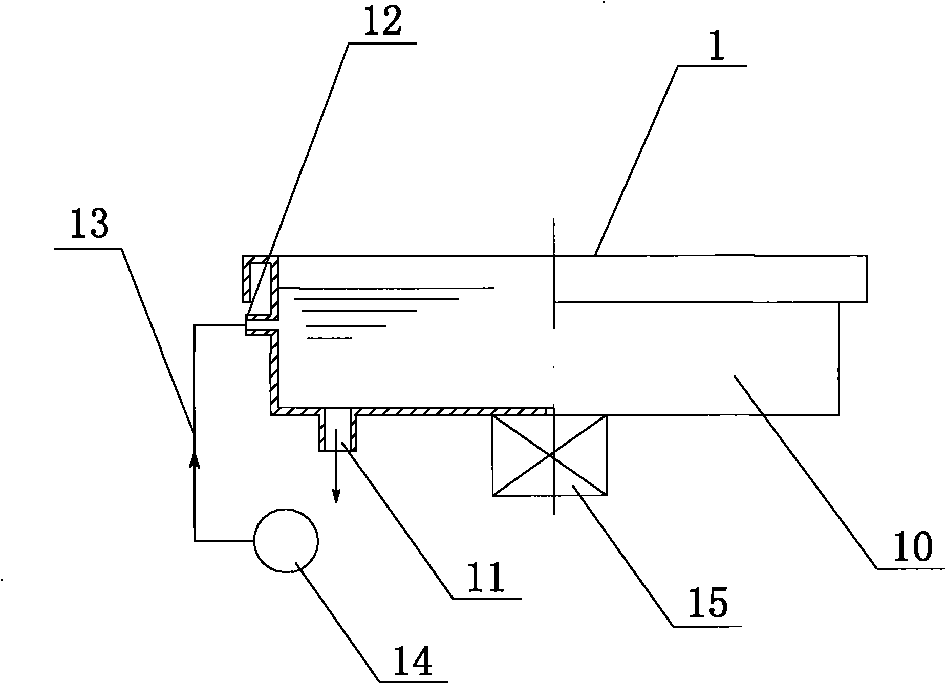
[0002] see figure 1 as shown, figure 1 It is a structural schematic diagram of a traditional ultrasonic hand washing machine. The traditional ultrasonic hand washing machine 1 includes a flushing tank 10, and the bottom of the washing tank 10 is provided with a water outlet 11, which is set on the side wall of the flushing tank 10 corresponding to the water outlet 11. There is a water inlet 12, the water inlet 12 is connected to the water delivery pipe 13, the water delivery pipe 13 is connected to the water pump 14, and the bottom of the flushing tank 10 is also provided with an ultrasonic vibrator 15, and when working, the water pump 14 pumps water to the flushing tank. In the tank 10, the ultrasonic vibrator 15 emits ultrasonic waves to vibrate the flushing water in the flushing tank 10 to achieve a flushing effect, and the flushing water can be recycled, but because there is no filter, the dirt in the recycled flushing water cannot be removed, and the flushing water When the washing tank 10 is used repeatedly many times, if a person with relatively dirty hands uses it, bacteria will remain in the washing tank 10 and the water delivery pipe 13, which poses a certain health and safety hazard, and the washing effect not good too

Method used


Image

  • Ultrasonic hand washing device
  • Ultrasonic hand washing device
  • Ultrasonic hand washing device

Examples


Embodiment Construction

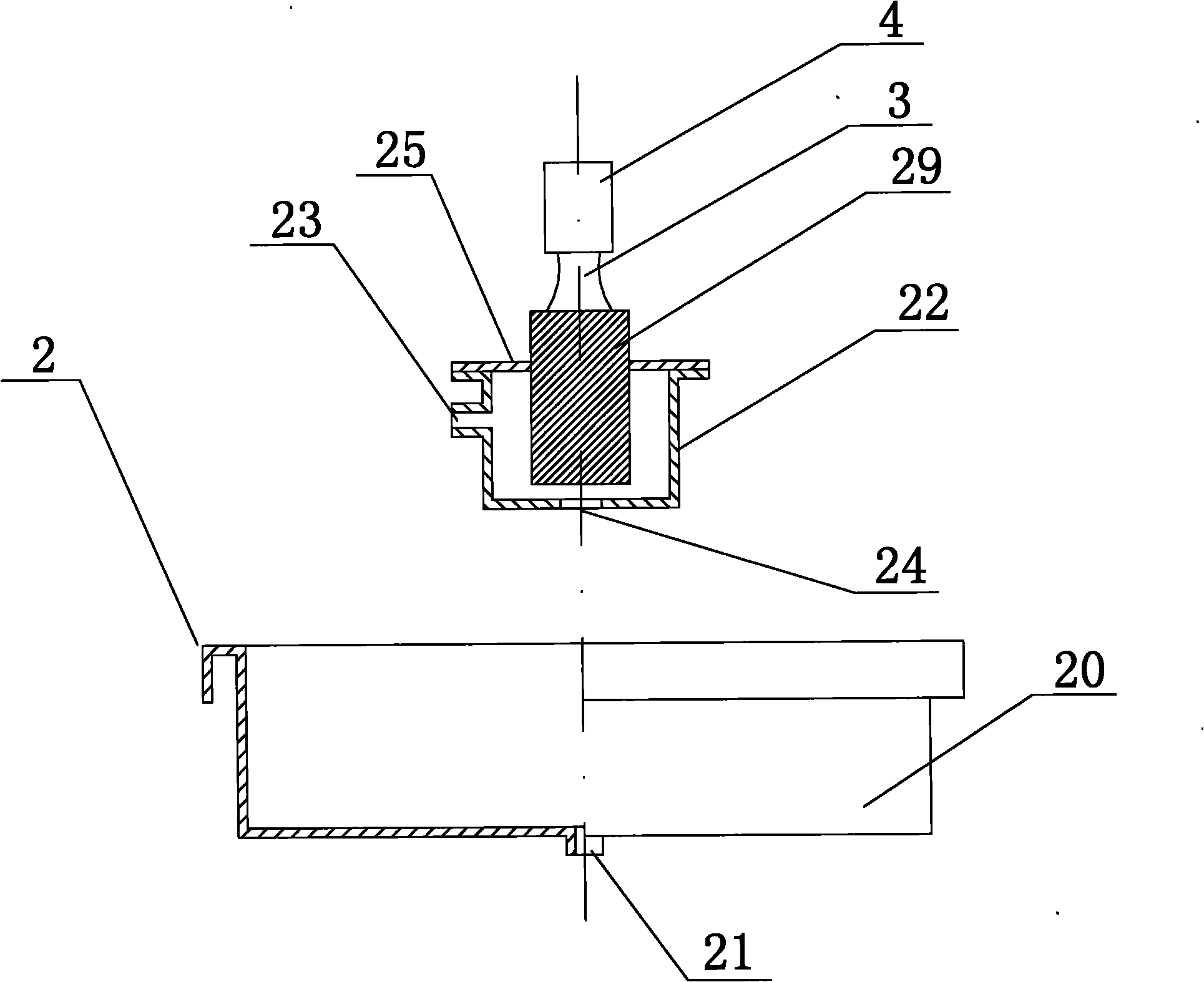
[0014] see figure 2 as shown, figure 2 It is a structural schematic diagram of an ultrasonic hand washing device of the present invention. In this embodiment, the ultrasonic hand washing device 2 includes a washing tank 20, and a water outlet 21 is provided at the bottom of the washing tank 20, and a water outlet 21 is provided above the washing tank 20 There is a water collecting tank 22, and the water collecting tank 22 is provided with a water inlet 23 and a hand washing port 24, and the top of the water collecting tank 22 is also provided with a horn button 29 that can vibrate up and down, and the horn button 29 is partially pierced It is inside the water collection tank 22, and the horn button 29 is connected to the ultrasonic vibrator 4 through the cone connection part 3. The power of the ultrasonic vibrator 4 is 200W, and its frequency is 30kHz.

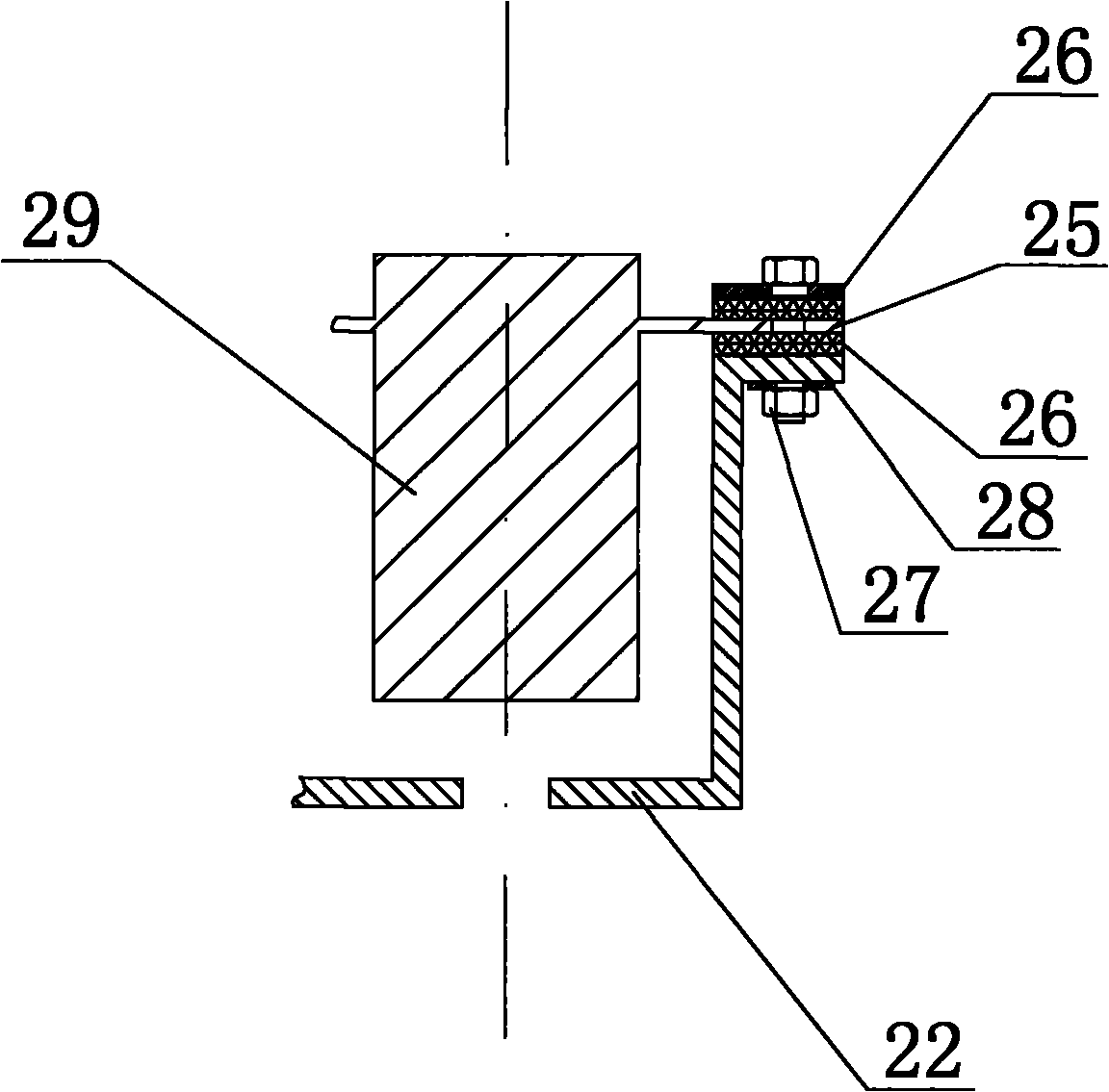
[0015] see image 3 as shown, image 3 It is a schematic diagram of the local structure of the water collection box of ...


PUM


Abstract

The invention discloses an ultrasonic hand washing device which is used in the medical institutions such as the hospital, the clinic and the like. The ultrasonic hand washing device comprises a washing tank. A water collecting tank is arranged above the washing tank; a horn button which can vibrate up and down is arranged on the top of the water collecting tank and is connected with an ultrasonicvibrator through a conical connecting part; one side wall of the water collecting tank is provided with a water inlet; the bottom of the water collecting tank is provided with a hand washing hole; the bottom of the washing tank is provided with a water outlet; the water collecting tank which is connected with the ultrasonic vibrator is arranged above the washing tank; and the ultrasonic vibrator is used for vibrating the washing water in the water collecting tank. The ultrasonic hand washing device can be used for washing the dirt on the fingerprints and the dirt in the pores and the fingernails. The ultrasonic hand washing device has simple structure and good hand washing effect and is highly sanitary and safe.

Description

technical field [0001] The invention relates to a flushing device, in particular to an ultrasonic hand washing device. Background technique [0002] see figure 1 as shown, figure 1 It is a structural schematic diagram of a traditional ultrasonic hand washing machine. The traditional ultrasonic hand washing machine 1 includes a flushing tank 10, and the bottom of the washing tank 10 is provided with a water outlet 11, which is set on the side wall of the flushing tank 10 corresponding to the water outlet 11. There is a water inlet 12, the water inlet 12 is connected to the water delivery pipe 13, the water delivery pipe 13 is connected to the water pump 14, and the bottom of the flushing tank 10 is also provided with an ultrasonic vibrator 15, and when working, the water pump 14 pumps water to the flushing tank. In the tank 10, the ultrasonic vibrator 15 emits ultrasonic waves to vibrate the flushing water in the flushing tank 10 to achieve a flushing effect, and the flushi...

Claims


Application Information

Patent Timeline
IPC IPC(8): A47K7/04B08B3/12
Inventor 姚建梁
Owner 姚建梁
Learn More