Steel mill of grain mill

A technology of milling machine and steel mill, which is applied in grain processing and other directions, and can solve problems such as difficult control and tediousness

Inactive Publication Date: 2010-08-18
上海宏麟电子科技有限公司
View PDF7 Cites 15 Cited by
  • Summary
  • Abstract
  • Description
  • Claims
  • Application Information

AI Technical Summary

Problems solved by technology

The current mill is more cumbersome to adjust the gap between the movable

Method used


Image

  • Steel mill of grain mill
  • Steel mill of grain mill
  • Steel mill of grain mill

Examples


Embodiment Construction

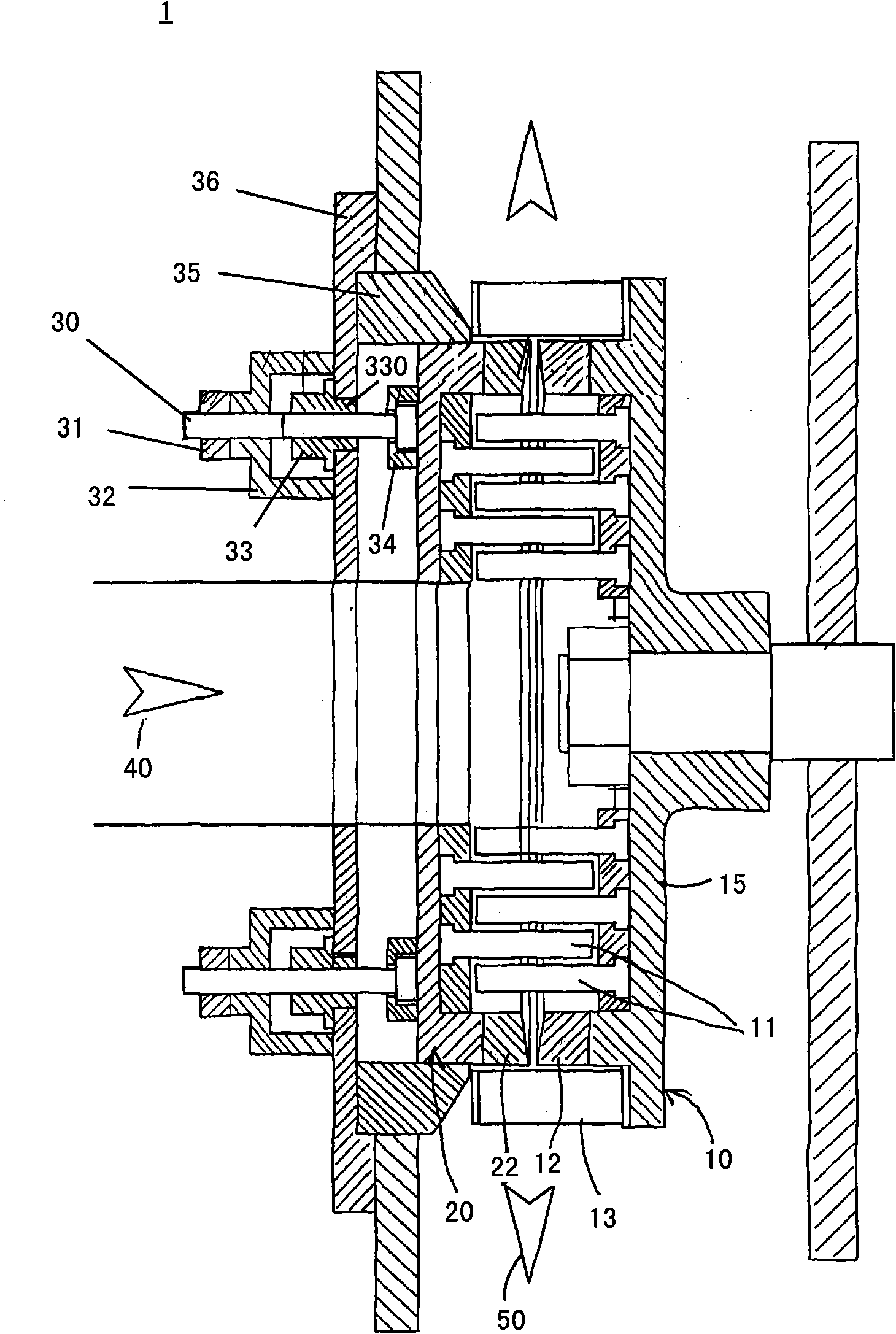
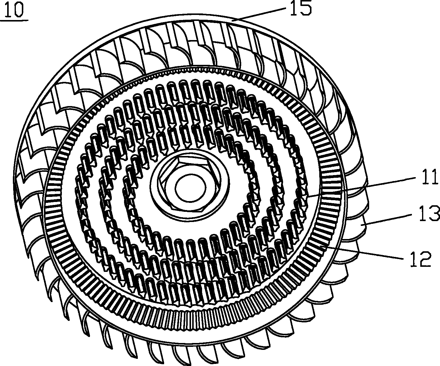
[0020] Such as Figure 1 to Figure 3 As shown, the steel mill 1 includes a movable cutter head 10 and a static cutter head 20 .

[0021] The movable cutter head 10 has a circular grinding knife 12 , multiple groups of pulverizing knives 11 and blades 13 arranged in a ring. The blades 13 are centrifugal blades. The grinding knife 12 , the pulverizing knife 11 and the blade 13 are all fixedly arranged on the flywheel tool holder 15 .

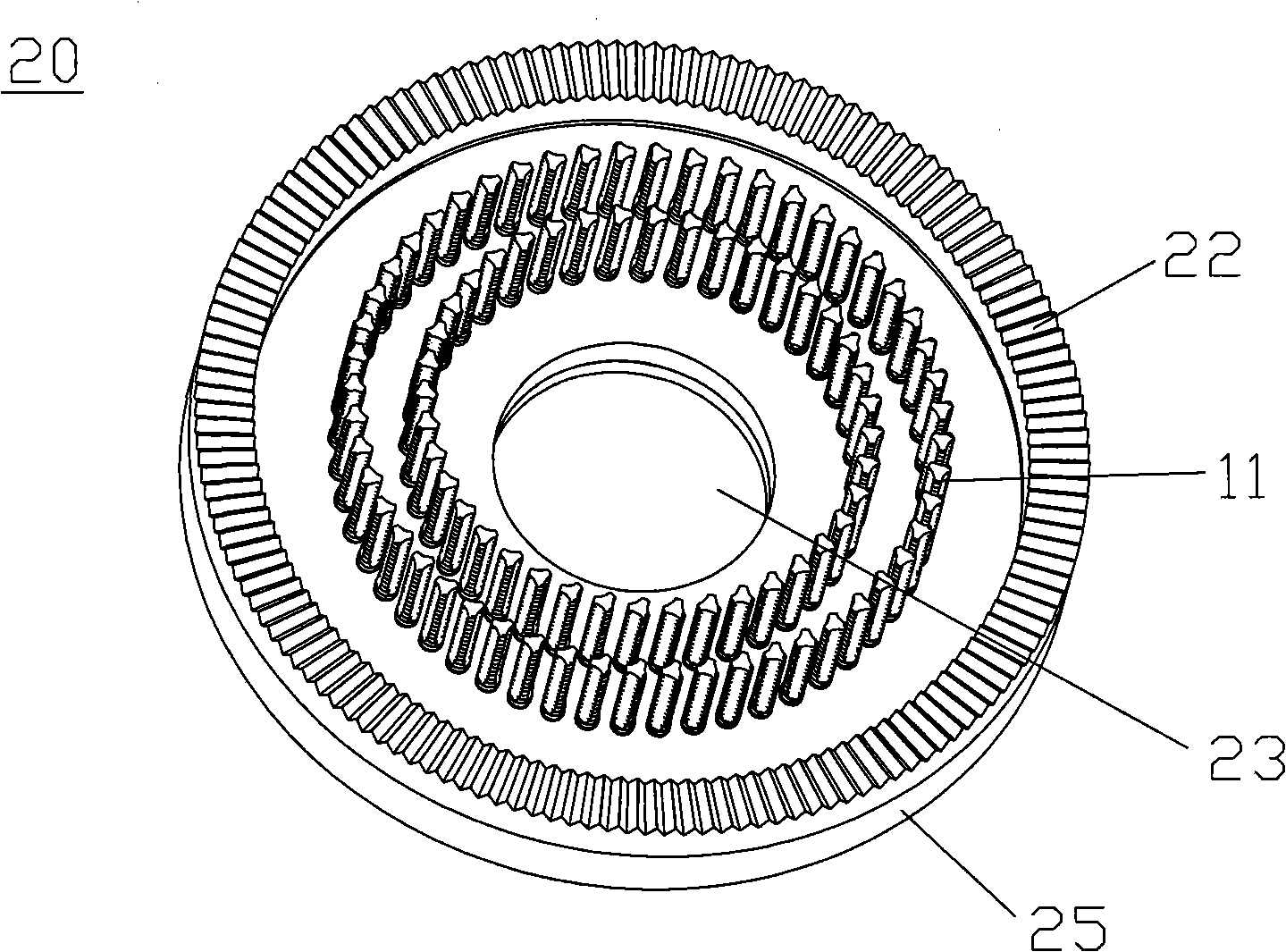
[0022] The static cutter head 20 has arc-shaped grinding blades 22 , multiple groups of pulverizing blades 11 and an opening 23 on the end surface. The grinding knife 22 and the crushing knife 11 are all arranged on the knife holder seat 25 . The end face opening 23 runs through the inner and outer end faces of the knife rest seat 25 and is arranged at the center of the knife rest seat 25 .

[0023] When working, the processing material enters the cavity formed by the movable cutter head 10 and the static cutter head 20 of the steel mill 1 acc...


PUM


Abstract

The invention discloses a steel mill of a grain mill. The steel mill comprises a movable cutter disc and a fixed cutter disc which are arranged at a predetermined gap, wherein the movable cutter disc and the fixed cutter disc are provided with grinding cutters respectively; the inner ring of the grinding cutter of the movable cutter disc is provided with at least one circle of crushing cutters; the inner ring of the grinding cutter of the fixed cutter disc is provided with at least one circle of crushing cutters; and the outer ring of the grinding cutter on the movable cutter disc is provided with a plurality of centrifugal blades which are arranged annularly.

Description

technical field [0001] The invention relates to a steel mill suitable for mills in the fields of plastics, rubber, food, medical treatment, chemical industry and the like. Background technique [0002] The mill is mainly composed of a main motor, a metal separator, a steel mill, a blower, a set of conveying pipes, a cyclone, an air shutoff, a vibrating screen, etc. When it is working, the main motor is driven by the steel mill (the steel mill has a feeding The processing material is added from the feed port of the steel mill, and the metal objects are removed through the metal separator (depending on the material to be processed, whether a metal separator is required), and then enters the grinding knife in the steel mill for grinding , under the action of the blower, the processed powder is sucked into the conveying pipeline, then the powder enters the cyclone, and then passes through the wind and enters the vibrating screen for screening. The qualified powder is packed, and...

Claims


Application Information

Patent Timeline
IPC IPC(8): B02C18/18B02C18/16
Inventor 陆国麟
Owner 上海宏麟电子科技有限公司
Why Eureka
Try Eureka