Swinging-focal spot roller surface laser texturing method and device
A laser texturing and processing device technology, applied in laser welding equipment, metal processing equipment, manufacturing tools, etc., can solve the problems of cold-rolled steel plates without obvious linear distribution, strain, etc., and achieve high laser energy utilization and low cost. , Improve the effect of rolling quality
- Summary
- Abstract
- Description
- Claims
- Application Information
AI Technical Summary
Problems solved by technology
Method used
Image

Examples
Embodiment 1
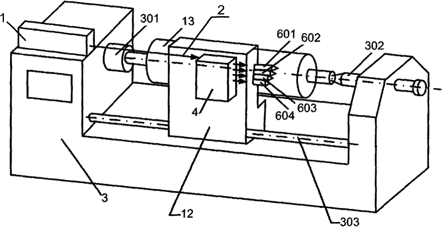
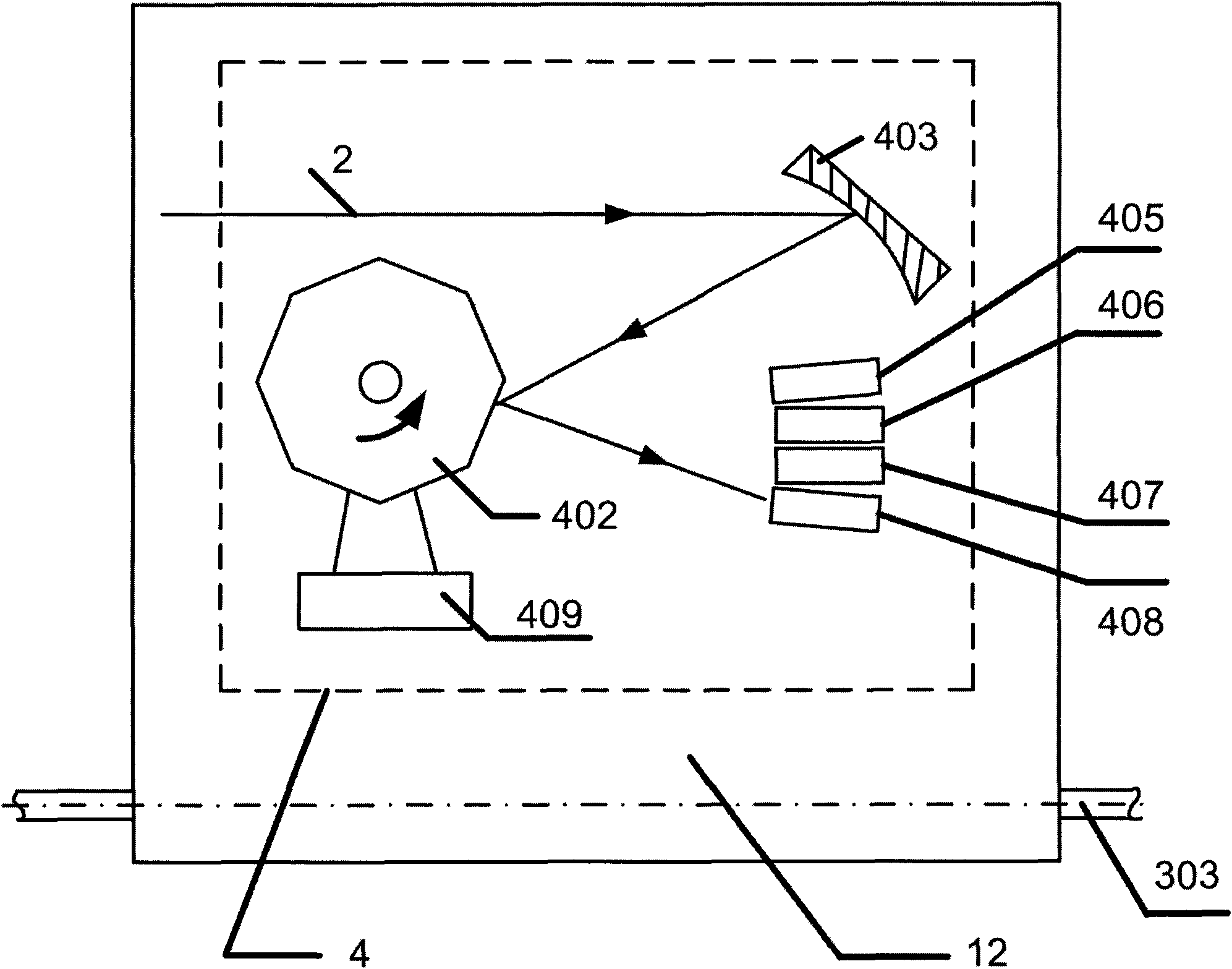
[0055] Example 1: Such as figure 2 Shown is a specific implementation of the laser texturing device for the surface of a roll with a focused spot swing of the present invention. It includes a laser 1 and a numerically controlled machine tool 3, the numerically controlled machine tool 3 adopts a conventional XL9 type numerically controlled machine tool, and its bed body A work platform 12 driven by a translational guide rail 303 and a roll shaft 301 and a top 302 for mounting the roll 13 are provided, and the roll shaft 301 and the top 302 are parallel to the translation guide 303. The working platform 12 is equipped with a polygonal scanning mechanism 4 and an integrated focusing mechanism. The integrated focusing mechanism consists of K=4 integrated focusing heads (respectively the first integrated focusing head 601, the second integrated focusing head 602, and the third integrated focusing head). Head 603 and the fourth integrated focusing head 604); and the laser 1 uses high...
Embodiment 2
[0065] Example 2: Such as figure 2 As shown, this embodiment provides the focusing spot swing type roller surface laser texturing processing device, its external structure is the same as that of embodiment 1, but the difference is that it uses the first reflection in the polygon scanning mechanism 4 of embodiment 1 The type focusing lens 403 is replaced with the first transmission type focusing lens 404, and the internal structures of the four integrated focusing heads 601, 602, 603, and 604 are all redesigned at the same time. Specifically, taking the first integrated focusing head 601 as an example, in this embodiment, a second transmission type focusing lens 7 and N=3 closely arranged focusing lenses 901, 902 arranged opposite to the second transmission type focusing lens 7 are arranged inside. 903, such as Figure 8 Shown ( Figure 8 The high-speed motor 409 and the four beam splitters 405, 406, 407, and 408 connected to the side of the polygon mirror 402 are omitted. The ...
Embodiment 3
[0066] Example 3: Such as figure 2 As shown, this embodiment provides the focusing spot swing type roller surface laser texturing processing device, its external structure is the same as that of embodiment 1, but the difference is that it uses the first reflection in the polygon scanning mechanism 4 of embodiment 1 The type focusing lens 403 is replaced with the first transmission type focusing lens 404, and the internal structures of the four integrated focusing heads 601, 602, 603, and 604 are all redesigned at the same time. Take the first integrated focusing head 601 as an example. In this embodiment, a second parabolic reflective focusing mirror 5 and N=3 closely arranged focusing mirrors 901 arranged opposite to the second parabolic reflective focusing mirror 5 are arranged inside. , 902, 903, such as Picture 9 Shown ( Picture 9 The high-speed motor 409 and the four beam splitters 405, 406, 407, and 408 connected to the side of the polygon mirror 402 are omitted. The w...
PUM
 Abstract
Description
Claims
Application Information
 - R&D
- Intellectual Property
- Life Sciences
- Materials
- Tech Scout
- Unparalleled Data Quality
- Higher Quality Content
- 60% Fewer Hallucinations
Browse by: Latest US Patents, China's latest patents, Technical Efficacy Thesaurus, Application Domain, Technology Topic, Popular Technical Reports.
© 2025 PatSnap. All rights reserved.Legal|Privacy policy|Modern Slavery Act Transparency Statement|Sitemap|About US| Contact US: help@patsnap.com