
Automatic gauge block calibrating device based on stepper motor

A technology of stepping motor and verification device, applied in the direction of measuring device, optical device, instrument, etc., can solve the problems of high skill requirements of measuring personnel, uneven force on measuring block, affecting measuring accuracy, etc., and achieve the effect of reducing cost

Active Publication Date: 2011-11-02
TIANJIN MICRONANO MFG TECH
View PDF0 Cites 0 Cited by
  • Summary
  • Abstract
  • Description
  • Claims
  • Application Information

AI Technical Summary

Problems solved by technology

This method has the following deficiencies: (1) Manually moving the gauge block and changing different measurement points will easily bring about temperature changes and affect the measurement accuracy, and the force on the gauge block is uneven, and the surface is prone to scratches, which affects the use of the gauge block (2) Only "one-to-one" measurement can be carried out, that is, one standard block corresponds to one tested block, which greatly limits the improvement of verification efficiency, and requires a large number of standard blocks, increasing the cost of measurement; (3 ) Since only one probe is used to measure the distance from a point to a surface, it cannot fully comply with the definition of the length of the gauge block in JJG_146-2003 (any point on one measurement surface of the gauge block is connected to the other measurement surface opposite to it) The vertical distance between the surface of the auxiliary body); (4) The manual method of estimating and reading the measurement data is prone to errors. Manually recording the parameters and evaluating the gauge blocks requires a large workload and requires high skill requirements for the measurement personnel.

Method used


Image

  • Automatic gauge block calibrating device based on stepper motor
  • Automatic gauge block calibrating device based on stepper motor
  • Automatic gauge block calibrating device based on stepper motor

Examples


Embodiment Construction

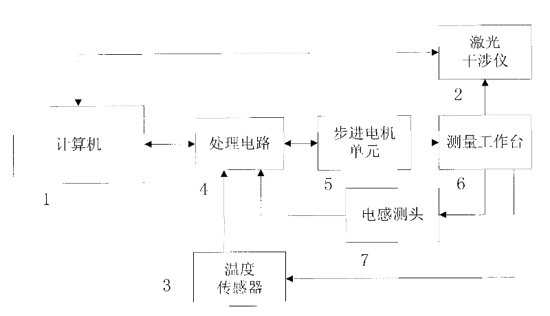
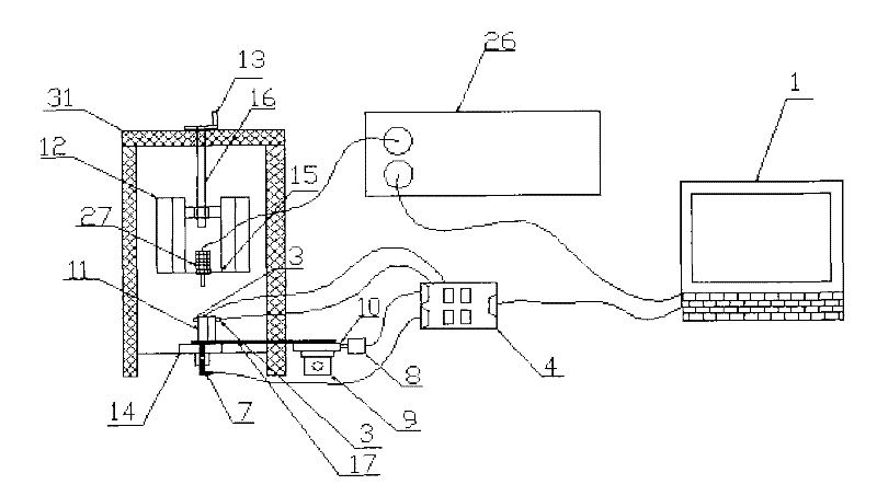
[0042] Specific embodiments are given below in conjunction with the accompanying drawings to further illustrate how the automatic verification device for gauge blocks based on stepping motors of the present invention is realized.

[0043] Such as figure 1 As shown, the automatic verification device for measuring blocks based on stepping motors of the present invention includes a computer 1, a laser interferometer 2, a temperature sensor 3, a processing circuit 4, a stepping motor unit 5, and a measuring block and a standard block Measuring workbench 6 and electric probe 7, wherein, described processing circuit 4 is connected with computer 1 by RS232, the input end of described stepper motor unit 5 is connected the processing circuit 4 that controls stepper motor work, output end Connect the measurement workbench 6 to drive the measurement workbench 6, the laser interferometer 2 and the electrical probe 7 are respectively clamped on the measurement workbench 6 for the detection...


PUM


Abstract

The invention discloses an automatic gauge block calibrating device based on a stepper motor, which comprises a processing circuit and a computer, wherein the processing circuit is connected with the computer, the input end of a stepper motor unit is connected with the processing circuit, the output end is connected with a measurement workbench for driving the measurement workbench, a laser interferometer and an inductance probe are respectively clamped on the measurement workbench for detecting a gauge block to be measured, the laser interferometer is connected with the computer to send measured signals into the computer, and the inductance probe is connected with the processing circuit to send the measured signals into the processing circuit; and a temperature sensor is arranged on the gauge block to be measured on the measurement workbench, and is connected with the processing circuit to send the temperature of the gauge block to be measured into the processing circuit. The invention realizes the requirements for automatically calibrating the gauge block. The invention realizes the one-to-many and point-to-point calibrating method, lowers the cost, realizes the automatic measurement point change, automatic thermal compensation and automatic data processing, improves the measuring efficiency, and can reduce the influence of human factors on the measuring process.

Description

technical field [0001] The invention relates to an automatic verification device for a gauge block, in particular to an automatic verification device for a gauge block based on a stepping motor controlled by a computer and a single-chip microcomputer. Background technique [0002] The traditional secondary gauge block verification device refers to a complete set of devices that use the secondary gauge block as a standard and use Ubbelohde interferometer, optical meter or other types of comparators to verify the third gauge block. At present, the contact interferometer used by most metrology institutions is based on the principle of light wave interference, and converts small size changes into the movement and measurement of interference fringes. This method has the following deficiencies: (1) Manually moving the gauge block and changing different measurement points will easily bring about temperature changes and affect the measurement accuracy, and the force on the gauge blo...

Claims


Application Information

Patent Timeline
Patent Type & Authority Patents(China)
IPC IPC(8): G01B11/00G01B9/02
Inventor 郭彤陈津平高顺民傅星胡小唐
Owner TIANJIN MICRONANO MFG TECH
Learn More